
Original assembly, no-rail reference, window and stop order
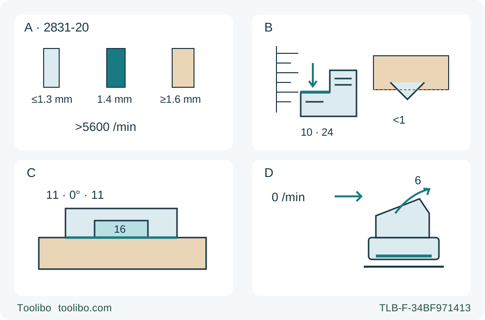
A shows blade plate at most 1.3 mm, knife 1.4 mm, kerf at least 1.6 mm and blade rating above 5600 rpm. B identifies the top of the lower single-line no-rail depth pointer and a partially projecting tooth. C shows original window 16 flush to stock and both bevel knobs 11 at zero. D puts zero rotation before front-handle return.
A · Verify the original identified wood system
Correct 165/20 mm blade rated above 5600 rpm, plate/knife/kerf match and both original knife clearances; known wood-only history or required service release.
B · Use the no-rail top edge
Battery removed: press slider button 24 and read the TOP of the lower single-line pointer 10. Through-cut and all conservative actual exposure limits must coexist.
C · Lock both ends and lower the window
While isolated set zero with both knobs 11, keep scoring disengaged and lower the original window 16 flush to the workpiece. Missing or unreliable window means hold.
D · Stop before returning the head
After normal completion release, wait for actual full stop, return the front handle upright and confirm coverage before safe setdown. Remove pack for measurement.
These are non-scale qualification diagrams, not fitting or live cutting poses. A also requires both already-correct knife clearances in the complete instructions. B highlights the no-rail pointer top edge; actual through-cut must satisfy less-than-full-tooth and less-than-1/8 in plus the 3 mm ceiling, a conservative conjunction of separate source statements. C retains the original mandatory viewing window, not an open aperture or alternative-guard installation. D means actual complete stop before front-handle return, guard coverage and safe setdown; it is not a two-second countdown.
The Milwaukee 2831-20 has several controls that can stop or change its downward travel: the depth pointer, scoring stop and blade-change mechanism do different jobs. Its viewing window is also a required operating component, not simply a convenience for seeing the line. This guide brings those distinctions into one complete no-rail, zero-bevel crosscut from an accessible edge of clean, dry, untreated loose wood. It ends with an isolated sample inspection, not a track installation or an internal plunge cut.
1. Establish the actual tool, history and original assembly
Match the physical 2831-20, its controls and supplied instructions to the current US product-linked 58140254d1 manual, dated 04/22. Read the complete instructions before using this guide. The 2831-21 kit is not a separate saw body or evidence of what came with your 2831-20. Do not infer a supplied blade SKU, charger, battery or rail from a neighboring kit listing.
Require a known wood-only service history or documented release by the specified Milwaukee service route. The manual requires a saw used for metal or masonry to be reserved and marked for that purpose, then returned to a Milwaukee service facility for cleaning and testing before wood use. Brushing off visible dust is not that release. Unknown prior use holds this wood task. The source also has differing dry-diamond and masonry-blade statements; none authorizes another material here.
Retain an already correctly installed, identified original blade suitable for this wood and its crosscut, with its actual blade instructions available. It must be 6-1/2 in/165 mm with a 20 mm bore, blade body no thicker than 1.3 mm and kerf at least 1.6 mm, matched to the 1.4 mm riving knife. The knife is thicker than the blade body and thinner than the kerf. Apply the manual’s stricter safe-speed wording: the blade rating must be ABOVE the tool’s 5600 rpm maximum no-load rating, not merely equal or reduced to a selected dial speed.
The original flange, bolt, blade orientation, knife alignment and clearances must already be correct. The manual separately limits the gap between knife and blade rim, and how far the rim extends below the knife’s lowest edge, to no more than 3/16 in. These are two checks, not permission to loosen either adjustment screw here. A bent knife, damaged teeth, dull blade, loose or wrong hardware, unknown assembly or an inaccessible qualification means hold for competent correction. No fitting, knife removal or fine-calibration procedure follows.
The knife remains installed for this ordinary edge-entry task. The manual’s separate interior-plunge section addresses starting in the middle when an edge cannot be used, and its safety text contains a knife-removal exception for plunge cuts. Do not stretch that exception into permission to disable the knife for normal edge entry. If the actual instructions or controls leave that distinction unclear, obtain manufacturer or qualified clarification before proceeding. The knife must engage the wood to function and is ineffective on short cuts; it does not guarantee freedom from kickback.
2. Inspect with the battery completely removed
Release the trigger and wait for complete blade standstill, then press the pack’s release buttons and pull it fully away. Remove the pack whenever the tool is not in use and before settings, inspection or maintenance. Lock-off button 4 prevents unintended triggering; it is not electrical isolation. Keep keys and loose metal away from exposed battery terminals.
Before every use, check the guard’s free movement, immediate blade enclosure, return spring and clearance from blade and other parts at all angles and depths of cut under the complete instructions. A drop warrants particular concern, but all-range clearance is not an after-drop-only requirement. Do not tie the guard open or invent an ordinary pendulum-guard lever for this plunge body. Sluggish return, interference or a failed spring requires service before use.
Inspect the switch, handles, shoe, locks, accessible original hardware and blade condition. Any damage, modification, misalignment, binding, unreliable switching or unexplained condition holds the task. The blade-change lever 23 must be in its normal operating state, not locking the assembly for service. If that state cannot be identified from the complete actual instructions, stop rather than forcing the front handle. Do not perform a powered test to reproduce a suspected fault.
Use only an actual sound M18 battery and its specified charger already commissioned under their complete matched instructions. This article approves no new named pair and gives no charging sequence. The tool’s recommended ambient operating range is 0°F to 125°F; the actual power-system instructions remain additional requirements, not replaced by that tool range. An adequately charged battery does not certify the tool’s condition. Keep the workplace dry, well lit, clear of bystanders and free of explosive or flammable hazards, with clean dry grips and stable footing.
3. Set zero bevel, no-rail depth and the viewing window
With the battery out, disengage the 22.5° stop and raise the original viewing window to its highest position. Loosen both bevel knobs 11, use the main handle to bring the actual pointer to zero, then tighten both knobs. This is not the -1°/48° override procedure, and the preset stop is not a substitute for locking both ends.
Press depth-slider button 24 and move pointer 10 along scale 9. For this no-rail cut, read the TOP edge of the lower, single-line side of the pointer. The higher double-line side is for a rail. Do not add a guessed offset or treat the lower edge of the pointer as the index. The stop limits the head’s downward travel; the actual original blade still determines exposure below the material.
Apply a deliberately conservative combined task gate: the blade must cut through the wood while exposing less than one full tooth AND less than 1/8 in, with the manual’s 3 mm ceiling also respected. The source uses less-than-full-tooth, no-more-than-1/8 in/3 mm, and an alternative wording in different sections; this conjunction is our stricter workflow choice, not a claim that the manual states a single identical sentence. Verify actual exposure while isolated, over clear space and without tooth contact. If through-cut, exposure and full return cannot all qualify, stop; do not turn a fine-adjustment screw or make a powered depth experiment.
Keep scoring stop 21 disengaged by pulling it back as described in the manual. This task is one through-cut, not the separate rail-dependent scoring process. After settings, lower the correctly installed viewing window 16 flush with the workpiece. A window or properly installed alternative splinter guard is mandatory during operation; this guide specifically retains the original window. Missing, damaged or unreliable retention is a hold, not permission to work with an open viewing area. Do not substitute an untrimmed accessory or teach its installation here.
4. Qualify the whole path and active extraction
Choose a manageable known wood blank, inspect the entire cut route and underside for nails, stones and other foreign material, and reject uncertain or coated stock. Mark a square crosscut across the grain from a reliable reference edge, clearly identifying retained stock and waste. The source’s capacity pairs are not exact conversions: 2-1/4 in is printed with 59 mm, and 1-5/8 in with 44 mm. Preserve those discrepancies; do not use a silently corrected maximum to approve this sample.
Clamp the retained work securely to a stable bench or sawhorses. Support both portions independently, including near the cut and edges where needed, while keeping the blade, knife and all moving parts clear. Waste must be free to separate without dropping dangerously or pinching the kerf. Never hand-hold the stock or catch the offcut. Establish shoe support through entry, travel and clear exit, plus space for returning the front handle after the blade stops.
With the pack removed and blade guarded, check reach and clearances beside or safely above the route without tooth contact. Do not push the blade into uncut wood during rehearsal. Both grips, clamps, window and hose must remain clear throughout. A setup that requires leaning into the blade line, moving a clamp mid-cut or cutting the supports is not ready. This workflow provides no universal overhang, minimum offcut or fixture certification.
The manual always requires a dust bag OR vacuum. This task selects a suitable actual extractor: with the pack removed, push and twist the matching hose onto the rear port, rotate the port for workpiece clearance and connect the other end to the qualified extractor. Operate and check that extractor under its complete instructions before the cut; an attached but inactive hose is insufficient. Product collection percentages or hose fit do not establish exposure compliance.
Wear ANSI Z87.1 eye protection and appropriate hearing protection. For dusty work, the manual requires appropriate respiratory protection OR an OSHA-compliant dust-extraction solution; this is separate from simply having a bag or vacuum connected. If extraction compliance is not established, retain suitable respiratory protection, along with adequate ventilation and control of bystander exposure. Do not infer safety from invisible dust. Collection care follows the actual extractor instructions; the manual’s warning about self-igniting coated-workpiece dust is another reason not to broaden this clean untreated-wood task.
5. Use the normal edge-entry sequence
Dial 19 runs from 1 to 6, with higher numbers giving higher speeds. The manual supplies the overall 2500–5600 rpm range, not a wood-setting table or a linear rpm map. Establish an appropriate known setting for the actual identified blade and material before connection. If you cannot establish it from the complete instructions, seek qualified advice rather than choosing a number by guesswork.
Confirm the trigger is released, all adjustments are secure, keys removed and the system ready. Slide the already qualified battery into the tool and verify that it latches securely. Keep hands out of the cutting area and from under the work. Use main handle 2 and front handle 6, with insulated gripping surfaces and body positioned to either side rather than directly behind the blade line.
Place the front of shoe 14 on the supported workpiece edge without blade contact. Align front and rear sight references with the cut line: position A indicates the inside edge of the cut at zero bevel without a rail. Position B serves the separate 45° case and is not the square reference. Press lock-off 4 down, then pull and hold trigger 3. Allow the selected full speed to develop before beginning the cut, slowly lower to the preset depth at the visible edge, then feed forward along the line. Keep the shoe flat and both grips firm. Advance without forcing or twisting; do not pull a moving blade backward to correct direction.
At normal completion release the trigger, wait for actual full blade stop, then return the front handle upright. Confirm the guard covers the blade before removing the saw and setting it down safely; remove the pack before measurement or raising the window after work. The electric brake generally stops the blade within about two seconds, but the manual explicitly allows delays or missed engagement. That is not a countdown or a substitute for observing standstill. Frequent brake failure requires authorized Milwaukee service, not repeated testing.
If the blade binds or any cut must be interrupted, release the trigger and hold the saw motionless in the material until it stops. Never lift or withdraw a moving blade from a trapped kerf. Isolate when safe and obtain appropriate correction or service. This guide does not provide the separate old-kerf restart, interior-plunge or recovery procedures.
6. Accept the process as well as the dimensions
After isolation, check complete separation, measured length, line straightness, through-thickness squareness, both faces and edge finish. Check that clamps, depth, bevel locks, window, knife and hose remained sound and that neither piece shifted or pinched the blade. Burning, smoke, unusual noise, binding, missing extraction or unexplained brake behavior overrides an otherwise correct dimension.
Record the actual material, original blade identity, settings and result. An unsuccessful sample requires cause assessment, not a loose-piece recut, new blade experiment or repeated restart. Keep the isolated tool clean and dry under the complete maintenance instructions; do not disassemble it, immerse any power component or use a solvent workaround. Use the specified service channel for repairs. A complete, sound sample qualifies only planning the next comparable ordinary cut, not a rail system or a different material.
Models referenced