
5477NB isolated qualification checkpoints
Four conceptual panels show the original 185 mm US assembly, separate depth and zero-bevel settings, A versus B sight references, and standstill followed by physical disconnection.
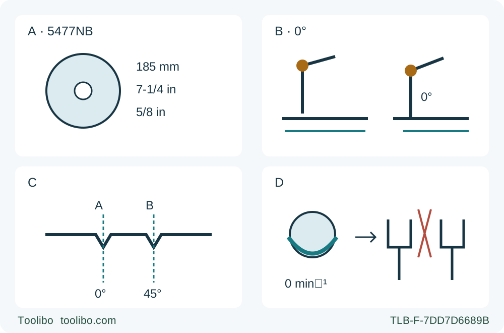
A · Original assembly
Confirm the actual qualified US original 185 mm / 7-1/4 in wood blade and 5/8 in regional arbor; the drawing is not a fitting or flange-reversal instruction.
B · Isolated settings
With the plug disconnected, set and lock the rear depth lever and front bevel lever separately. Use zero bevel and less than a full tooth below the work.
C · Square reference
Use A for square cuts, not B for 45 degrees; qualify the actual kerf and straightedge contact on supported scrap.
D · Stop and disconnect
Release the trigger, wait for complete blade standstill and lower-guard coverage, set down safely and unplug before inspecting. Zero rotation is not physical isolation.
All adjustment and inspection panels refer to an unplugged tool. A is assembly identity, not a replacement recipe; B does not locate the levers to scale. C preserves the manual A/B reference relationship. D separates blade standstill from unplugging. No panel depicts a running cut or an oil-service procedure.
This workflow prepares an existing US Makita 5477NB for a supported square cut in known, dry, nail-free loose wood. The outcome is a verified original assembly, a secure zero/depth setup and an accepted sample—not a demonstration of maximum power, a flange conversion or a gear-service lesson. Match the actual nameplate and supplied instructions to manual 884849A941 / 5477NB-1, which the current US product directly links.
Makita identifies this model as a hypoid saw. That name is documentary evidence about the body, not a reason to infer operating instructions from another rear-handle saw. In particular, do not borrow an oil-level procedure, electric-brake promise or lock-off control from a different model. The exact front and rear handles, separate adjustment levers and A/B cut references matter more to this task than the shape of the handle alone.
Qualify the original US assembly without changing it
The manual specifies a 185 mm (7-1/4 in) blade and 4500 rpm no-load speed. Keep those units as documented; do not silently rewrite 185 mm as another model’s 184 mm specification. The current US product lists a 5/8 in arbor, while the manual also describes a reversible inner flange, a second hole size and Ring 17. This workflow does not reverse that flange, move the ring or select a replacement blade.
Require the already correctly assembled original, manufacturer-approved wood blade, matching mounting parts and known service history. A blade that looks approximately the right diameter or has a round hole is not enough. Visible damage, inappropriate teeth, dullness, unusual washer arrangements or uncertain assembly means stop for complete exact instructions and qualified correction. Do not dismantle the assembly merely to turn an unknown arrangement into an apparently complete checklist.
The current product’s blade marketing mentions nail-embedded wood, but the manual specifically says to avoid cutting nails and to inspect and remove them before cutting. This sample is nail-free. Reject hidden fasteners, suspect coatings, unknown composition and wood that cannot be supported securely. Damp, treated or knotty material calls for extra attention in the manual and is outside this straightforward first sample.
Choose manageable stock within the actual original blade and the documented square-cut capacity. The manual gives 60 mm at 90°, but a maximum is not a recommended sample thickness or a reason to project the blade deeply. A good sample allows safe clamping, continuous retained-base support and an unambiguous dimension to measure afterward.
Establish supply, isolation and the working area
Release the trigger, wait for complete blade standstill and unplug before checking functions, setting depth or bevel, arranging guides or clearing the tool. Keep the disconnected plug under control. Inspect the actual cord and plug for damage and make sure the supply agrees with the nameplate. A product’s 15 A listing does not establish every owner’s voltage or make any extension lead suitable.
If an extension is needed, use the exact manual table for the actual nameplate current, voltage and total length. For example, only when the real setup is 120 V and within the table’s over-12-to-16 A row does it specify 14 AWG at 25 ft and 12 AWG at 50 ft, with 100 and 150 ft not recommended. These are conditional table entries, not a universal cord prescription. A different supply or unresolved requirement needs the correct documentation, not an adapter or guessed gauge.
Work in a dry, well-lit area away from flammable liquids or gases and bystanders. Wear eye protection, hearing protection and suitable dust protection; provide ventilation and follow the material’s safety information. Where dust-collection devices are provided, connect and use them correctly under their instructions. This selected manual does not establish a tool-port retrofit, hose diameter or installed airflow threshold, so do not invent one. If dust cannot be managed adequately in the location, change the plan instead of treating a mask as permission to cut anything anywhere.
Inspect the guard and trigger without power
Use the lower-guard retracting handle as instructed to check that the guard moves freely, closes instantly and touches neither the blade nor other parts at all angles and depths of cut. Check the spring’s operation and condition. The guard must operate automatically for the normal edge-entry cut; do not tie it open, hold it clear throughout the cut or test a known sticking guard by powering the saw.
A damaged guard, loose adjustment, damaged housing, abnormal switch or unknown original assembly keeps the tool out of service. The manual requires damaged tools to be repaired before use and qualified service with appropriate replacement parts. A smooth unloaded motor sound cannot certify those conditions. This article does not open the housing, clean a blade with chemicals or adjust a spring.
Before reconnecting later, check that the trigger moves properly and returns to OFF when released. The documented operation is simply pull to run and release to stop. Do not invent a separate lock-off step or a switch-lock arrangement. Remove any adjustment tool and keep both designated gripping surfaces clean and dry.
Set square depth with the separate levers
With the saw unplugged and stable, loosen the lever on the rear depth guide, move the base to the required depth and tighten the lever securely. Use the actual stock thickness to verify projection. The general safety section says less than a full tooth below the work, while the depth paragraph says no more than one tooth; use the stricter less-than-full-tooth setting here. Do not accept a depth scale reading without checking the physical cut envelope.
The bevel adjustment lever is at the front of the base on the bevel scale plate. Set the normal 0° position and tighten that lever securely. It is separate from the rear depth lever, so securing one does not establish the other. Recheck both and confirm lower-guard clearance after the setting changes.
The 45° stopper belongs to the bevel-range controls; it is not a substitute for the front locking lever. This square sample does not require the high-angle range or a 45° cutting procedure. Likewise, the factory accuracy-adjustment screws are not routine setup knobs. If a properly secured zero setup produces an out-of-square sample, stop for the complete correction instructions or qualified service rather than turning a screw experimentally.
Plan the supported route and the A reference
For this model’s straight cut, use position A at the front of the base; position B is the 45° reference. Confirm the actual kerf with a trial rather than assuming that the notch or a drawn line is the finished dimension. If using a straightedge, establish the actual blade-to-base-contact offset with the same assembly and zero setting. An offset from a blade-right Makita or another rear-handle saw does not automatically transfer.
Clamp the retained work to a stable support. The wider portion of the base must remain on the solidly supported piece, not the waste that will fall away. Independently support retained and waste portions outside the tooth path so the work cannot sag and close the kerf. Let waste separate without trapping it against the blade. Never hold a short piece by hand or put a hand below the work to catch it.
Check the full travel, including entry and exit, for clamp interference, underside clearance, guide contact and cord snagging. Keep the cord away from the cut so it cannot pull the tool or be severed. With the saw unplugged, assess reach beside or safely above the route, blade guarded and teeth clear of the stock. Do not drag projected teeth through uncut wood as rehearsal. If the far end requires overreaching or a mid-cut support change, rearrange the setup first.
Make the sample and require an actual stop
After every isolated check passes, confirm OFF and reconnect the matching supply. Hold the front grip and rear handle firmly with both hands, body beside rather than in line with the blade. Place the base on supported work with the blade clear of the material. Pull the trigger, wait for full speed and advance gently forward while keeping the base flat and the line of travel straight.
Do not force the feed to overcome resistance or twist the blade back toward a missed line. If binding or interruption occurs, release the trigger and hold the saw motionless until the blade stops; never pull a moving blade backwards from the kerf. Unplug before investigating. Restarting or salvaging that interrupted cut is outside this initial owner sample.
At normal completion, release the trigger and retain control until the blade has completely stopped and the lower guard has closed before setting the tool down safely. Do not apply side pressure to stop the blade, and do not use a countdown borrowed from a braked model. Unplug before measuring or clearing material.
Measure the intended dimension, square edge and finish, and inspect the process record: both locks stayed secure, the base remained supported, the guide did not shift, the cord stayed clear and the waste separated without pinching. A dimensional pass cannot excuse lost control or a guard problem. Resolve ordinary isolated setup issues under the full instructions; unexplained behavior or damaged parts remain a hold.
Keep maintenance claims within the actual documents
The product’s oil-bath and sealed-gear description is not a lifetime maintenance-free promise or an instruction to open or lubricate the gears. Do not transfer the SPT77’s pre-use oil procedure to this hypoid body. The 5477NB manual still contains inspection and maintenance obligations; this guide refers repair, brush work and other qualified adjustments to the appropriate complete instructions and service.
Store the tool unplugged in a secure place out of reach of untrained users. Keep the accepted sample record with the actual blade identity, zero/depth setting, guide relationship and support plan. It demonstrates one qualified wood-cutting setup, not permission to cut nails, change the reversible flange or assume another saw’s brake, dust attachment or maintenance schedule.
Models referenced