
Four controls and evidence checks before the sample
A shows a detached BSL36B18 battery, B separate depth and incline locks with a partial tooth below stock, C the right zero-notch edge, and D mode documentation separate from work-light warning pulses.
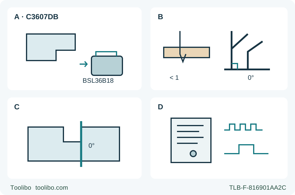
A · Physically isolate
Release the trigger, wait for full standstill, then press both battery latches and withdraw the actual BSL36B18 before settings or inspection.
B · Keep controls separate
Set actual less-than-full-tooth depth with its lever and zero bevel with the incline lever; secure both. Do not confuse either with the spindle lock.
C · Use the zero reference
Use the RIGHT side of the front notch for a square cut and verify actual same-assembly offset on scrap.
D · Recognize, do not program
Require a known previously qualified mode. Tool-light overload and overheat signals are separate evidence, not mode-selection or return-to-use permission.
These isolated recognition diagrams are not operating or installation instructions. B shows less than a whole tooth schematically, without a scale or lever-direction promise. C marks only the zero-bevel reference. D distinguishes prior mode evidence from warning-signal recognition; it does not show mode activation, physical LED colors or a reset.
This workflow takes an already commissioned US Metabo HPT C3607DB from isolated condition checks to one measured square wood sample. It uses the North American C99749561G / 306 manual, whose stylesheet identifies July 2023. Match the actual body, nameplate, supplied instructions and controls before proceeding. C3607DA, a HiKOKI regional counterpart or the Q4 package name is not an interchangeable operating identity.
The mode must already be known and correctly commissioned. The manual does not describe a selector that can simply be programmed with the battery removed: it says mode changes become available after battery installation and a trigger operation. This guide therefore does not teach trigger priming or an unknown-mode setup. If the prior configuration is uncertain, stop and resolve it through the complete actual instructions or qualified assistance before using this bounded owner route.
1. Admit the original assembly and exact power system
Retain an already correctly fitted genuine Metabo HPT sharp, undamaged wood blade and original matching washers and bolt. The manual specifies 7-1/4 in (185 mm) diameter and a 5/8 in (15.9 mm) hole; the actual blade diameter must match the product nameplate, its rating must suit the 6,000 rpm maximum no-load speed, and a wood blade must comply with EN 847-1. Do not substitute an abrasive wheel, a blade for spark-producing material or a guessed washer arrangement.
There is a real document boundary: the manual’s standard blade is 115750M, while the current US product page lists 115757M. That does not establish replacement equivalence or the contents of your carton. This is an original-qualified-assembly workflow, not a fitting tutorial. If the installed blade, mounting security or provenance is uncertain, hold the saw for complete model-specific qualification rather than partly following a blade-change diagram.
For this route, the actual genuine BSL36B18 battery and UC18YSL3 charger must already have been commissioned under their complete supplied instructions. The saw manual explicitly names them; broad MultiVolt marketing is not approval for every old battery. It specifically excludes BSL3660/3626/3620, BSL18 and BSL14 series. We do not equate current retail battery codes with the named battery merely because capacities look similar.
Use the tool and battery only between 23°F (-5°C) and 104°F (40°C), as the manual requires; this is the operating range, not a charging-temperature instruction. No charging, USB or ET36A AC-adapter procedure is included. The manual contains differing charging temperature and between-charge rest statements; this article does not silently reconcile them into a new charging recipe. A damaged, modified, leaking or otherwise abnormal battery or terminal condition fails the gate. Do not conduct a powered test to discover whether a suspect pack will work.
2. Isolate, inspect and identify the controls
Release the trigger and wait for complete blade standstill. With the switch OFF, press the battery’s two latches and withdraw the battery fully before inspection, adjustment or care. A dark lamp, an unpressed trigger or a mode selection is not physical isolation. Keep loose metal away from detached battery terminals.
Check the handles, housing, base, blade condition, fasteners, battery mount and switches. Remove the saw from use if there are cracks, damage, loose or uncertain mounting, abnormal switch action or terminals deformed or contaminated in a way you cannot safely correct under the instructions. The manual directs abnormal operation and repairs to an authorized service center.
Before each use, the lower guard must move freely and close instantly. Using its retracting handle with the tool isolated, verify that it does not contact the blade or another part at all angles and depths of cut; the spring must function properly. Do not tie it open or continue with sluggish movement. Guard faults require repair before use. Return the hook to its storage position until it latches against the saw body; this route does not use the hook for hanging.
Distinguish the cutting-depth lever, the incline lever and the separately named lock lever. The lock lever is the spindle lock, not a depth control, and must never be pressed while the motor is running. A control’s familiar shape is not sufficient identification.
3. Prepare a square sample with continuous support
Use known dry, untreated loose wood with no nails or other foreign material along the entire route. Reject unstable, badly warped or unidentified stock. Work in a clean, well-lit, ventilated area away from bystanders. Wear ANSI Z87.1 eye protection with side shields and a suitable mask or respirator; the manual requires hearing protection for extended operation. Do not wear cotton, wool, cloth or string gloves liable to roll into moving parts. Keep loose clothing, hair and jewelry clear.
Clamp the retained work to a stable platform. Independently support both portions near the cut and their edges, outside the blade path, so the waste can separate without pinching the kerf. Keep the wider base on the solidly supported retained portion. Check the entire underside and exit path; do not hold short stock in your hand or across your leg. Reposition the whole work before starting if you cannot finish with stable footing and both hands on the saw.
With the battery removed, loosen the cutting-depth lever. Hold the base and move the body relative to it to set depth, then tighten securely. Verify actual projection below the work: less than one full tooth, not maximum available capacity. Loosen the separate incline lever, set the base for a square cut and tighten it securely. Confirm the intended square relationship and later verify it on the sample; this guide does not adjust the factory calibration screw or teach a 55-degree cut.
Use a securely clamped straightedge for the sample rather than assembling an optional rip fence from a partial parts list. For zero bevel the manual uses the RIGHT side of the front notch; the left side is the 45-degree reference and is not used here. Establish the actual base-contact-to-cut offset with a same-assembly scrap trial. Mark the retained boundary and place the blade’s kerf on the waste side. Neither the notch nor a remembered offset proves final size without checking the resulting cut.
This workflow requires an existing correctly fitted approved dust collector 380086 secured with its M4 screw, connected to the actual suitable vacuum hose. With the saw isolated, verify the connection and route. Operate and check the vacuum under its own instructions before cutting. Keep the hose clear of the guard, clamps and feet through the full travel; do not release a hand to untangle it during a cut. The source gives no universal installed airflow threshold or automatic equivalence to another brand’s adapter. Extraction does not replace the manual’s respiratory protection requirement.
4. Understand the known mode without programming it here
In Auto Switch mode, the manual specifies 6,000 rpm no-load and describes an automatic change under increased load, with return when load decreases. When High Torque is deliberately selected, the mode lamp lights and the selected mode does not return to Auto Switch merely because load falls. The selection persists through switch cycles and battery removal.
Do not turn those descriptions into a force test. The manual gives 4,500 rpm for High Torque; the current product table says 4,300 rpm. Both attributions remain unresolved. Neither figure is a feed-rate target or justification to overload the saw. Use only the already known, qualified mode appropriate to the task. Unknown configuration, unexpected behavior or a need to change mode outside your complete understood instructions is a hold. Do not squeeze the trigger just to make the selector available under this simplified workflow.
The mode lamp is also different from the work-light warning signal and the battery gauge. Do not look directly into the LED light. A lamp illuminating is not confirmation that the blade, guard or workholding is safe.
5. Complete the required sound-tool check, then cut
Only after the isolated checks, settings, support and dust arrangements pass, keep the trigger released and align the qualified battery with the handle groove. Insert it fully until it clicks and verify secure locking. The manual’s insertion warning and troubleshooting restart wording differ; the safe common prerequisite is always OFF before insertion, not reliance on an anti-restart feature.
The manual requires proper electric-brake operation before use. For an otherwise sound tool, perform the deliberate normal on/off check under the complete instructions with the blade clear of work and obstacles, lower guard closed and firm two-handed control. Press the lock-off from either side and pull the trigger; releasing the lock-off while continuing to hold the trigger does not stop the saw. Release the trigger and confirm proper braking and actual full standstill before positioning for the sample. This is not a timed stopping test or permission to energize a suspected fault. A brake that does not function properly requires an authorized service center; do not repeat the check to reproduce the failure.
For the cut, grip the main handle and sub-handle securely, with your body to one side rather than in the blade line. Place the base on the supported work with the blade clear. Start using the lock-off and trigger, allow full speed before contact, and advance straight at a steady, unforced rate with the base flat. Do not twist to chase the mark, press the spindle lock or keep feeding a stalled blade.
If binding or interruption occurs, release the trigger and hold the saw motionless until complete standstill. Isolate it before investigating; do not pull a moving blade backward or improvise an old-kerf restart. An abnormal noise, damaged assembly or unexplained shutdown ends this sample route pending assessment. Normal completion likewise requires trigger release and full stop before withdrawing, guard coverage before stable setdown, and battery removal before inspection.
6. Accept the process as well as the edge
Measure the retained dimension at the intended datum, check edge straightness and squareness, and inspect both faces for unacceptable splitting, burning or unintended damage. Confirm that the guide, depth and incline locks stayed secure, the base remained supported, and the waste separated freely. A correct dimension does not excuse a loose lock, hose snag or abnormal stop; do not approve another cut until the cause is resolved.
The tool work-light table identifies 0.1-second on/off flashes for overload and 0.5-second on/off flashes for overheating. Battery display patterns are separate, including low charge, high temperature and failure. Record what actually occurred rather than substituting a charger-light interpretation. Release the trigger immediately when protection acts; follow the complete corrective instructions and seek service for abnormal or unresolved conditions. This article supplies no reset sequence or automatic return-to-use clearance.
After isolation, inspect for damage and dust accumulation. Use the manual’s permitted gentle external cleaning, not solvent experimentation; do not turn its air-gun, calibration or service sections into abbreviated repairs. Keep the tool and battery dry, secure and away from children under their storage instructions. The completed outcome is a measured acceptable square sample with known mode and sound controls—not proof of claimed torque advantage or approval for a different blade, battery or operation.
Models referenced