
Four independent GKT owner gates
Main battery and separate coin cell; partial tooth and two zero-angle locks; six-speed document with 5500 rpm; connected 35 mm extraction and return symbol.
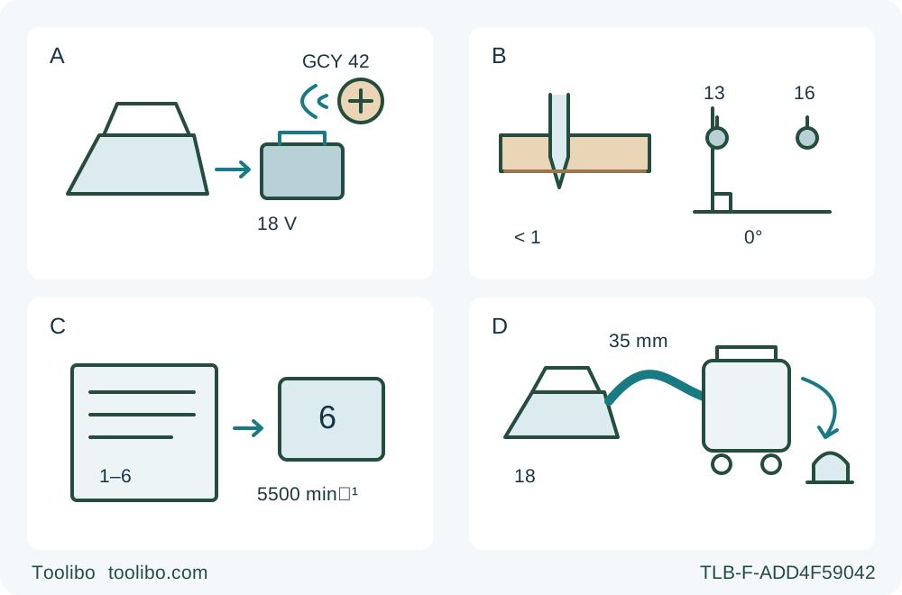
A · Separate the two power questions
Release the trigger, wait for standstill and fully remove the main battery. The installed GCY 42 has a separate coin cell; this is not a module-removal diagram.
B · Measure actual rail-free projection
With the main battery removed, verify less than a full tooth below the actual work and secure both bevel bolts at zero. The depth indicator assumes a Bosch rail; no numeric offset is supplied.
C · Require a known profile
The conceptual document and display refer only to the unmodified six-speed default profile, original T42 and solid softwood: level 6 is 5500 rpm. A displayed digit alone cannot establish configuration.
D · Connect extraction and understand return
The 35 mm hose connects ejector 18 to the suitable active extractor. The separate return symbol is conceptual recognition of enclosure, not an operating, fitting or reset sequence.
Original conceptual controls drawing, not to scale. All mechanical setup recognition assumes the main battery removed. A does not show module removal; B supplies no guessed rail offset; C is not an app or selector procedure; D is not a running cut. Actual guard enclosure and standstill are both required.
This workflow ends with an inspected square cut in a loose, supported softwood sample, using an already qualified GKT 18V-52 GC without a proprietary guide rail. Its two unusual prerequisites are a known speed configuration and an understood plunge-return mechanism. A battery, a lit display and a straight board are not enough to establish either.
Match the regional machine and its existing system
Match the actual Middle East machine to order 06016B4000, tool number 3601FB4000 and the A48 manual dated 21 January 2025, whose technical table covers 3 601 FB4 0.. . Read the complete supplied instructions, including the actual battery, charger, extractor and installed GCY 42 instructions. This is not permission to transfer a different regional model, an older manual or a GCY 42 NC module into the workflow. The English service addresses do not change the regional identity.
Retain the correctly installed, undamaged original Expert for Wood T42 assembly. Its qualification must already establish the correct 140 mm diameter, 20 mm bore, 1.0–1.4 mm blade body, no more than 2.4 mm tooth thickness/offset and permitted blade speed above the saw’s 5500 rpm maximum. Do not substitute motor speed for blade rating, infer compatibility from diameter alone, or loosen the blade bolt to identify parts. If markings, fitting history, flange condition or blade suitability cannot be established, stop for complete matched instructions and qualified correction. This is not a blade-changing procedure.
The actual genuine GBA 18V or ProCORE18V battery and its manufacturer-listed charger must already be commissioned under their complete instructions. A48 lists GAL 18, GAX 18 and GAL 36 charger families; that is not a newly verified pairing of every individual pack and charger. The ProCORE18V 5.5 Ah recommendation concerns maximum performance, not a universal minimum safety capacity. Reject damaged, modified or uncertain power systems. Observe the permitted operating/storage range of −20 to +50 °C; performance is limited below 0 °C. Charging has separate conditions and is outside this task.
Isolate the motor without mistaking that for radio isolation
Release the trigger, wait for complete blade standstill, then press battery release 22 and withdraw the main battery completely without force. Its two retention levels mean a partly released pack is not removed. Keep the pack protected from metal objects that could bridge its contacts. All guard, depth, bevel, guide and hose checks below are made with this main battery removed.
An installed GCY 42 has its own coin cell. Removing the main pack does not turn off that radio. Use this workflow only where wireless operation is permitted and the existing module, cover and configuration are already qualified. A48 prohibits Bluetooth use near medical devices such as pacemakers or hearing aids, petrol stations, chemical plants, potentially explosive atmospheres and blasting areas, and in aircraft. Avoid extended use near your body. A48 requires both module and coin cell removal in prohibited wireless areas; this article does not teach that service operation. Do not bring an uncertain system into such an area or improvise a way to disable it. Obtain the complete prescribed instructions or qualified help.
Keep coin cells away from children. A damaged or insecure cover is a stop condition, not something to tape shut. Suspected ingestion requires immediate medical attention. Do not recharge, short-circuit or damage the cell. None of these precautions calls for opening a sound installed module during the cut setup.
Understand the return mechanism before setting depth
The GKT is a plunge saw, not a conventional saw whose lower guard is manually swept aside. Lock-off 2 both permits starting and releases the plunge function. Lowering the saw body deploys the blade; allowing the body to rise returns it to its home position and locks the plunge function again. Blade-change lever 3 is not the normal operating release.
With the main battery removed, verify the guard moves freely and encloses the blade immediately, with no contact with blade or other parts at all cutting angles and depths. Check the return spring’s operation and condition. Keep fingers out of the blade path; never tie the guard open or force a sticky mechanism. Damage, delayed enclosure, failed spring action, uncertain switch operation or evidence of a fall requires service before use. Return the machine to the square setting after its checks.
Set the base fully on a level support. Loosen both bevel wing bolts 13 and 16, set zero on scale 11 and secure both. Do not twist the auxiliary handle or body to force the two ends into different angles. If they do not agree, stop and resolve the setting under the complete instructions rather than adjusting calibration screws 48 or 49.
Depth slider 36 works with scale 10, but indicator 7 reads depth with a Bosch guide rail. Without that rail, actual penetration is greater by the rail’s thickness. Do not simply add a guessed 6 mm correction or use a number from another Bosch saw. With the tool isolated and supported so no tooth touches stock or a fixture, establish the actual depth relative to the measured work thickness. Leave less than one complete tooth projecting beneath the work and secure the setting. If this cannot be verified safely, do not cut.
A48 also gives a thickness-plus-tooth-height instruction; this workflow keeps the stricter less-than-full-tooth requirement stated in its safety and depth sections. Its 45° capacity/scale statements are not reconciled here: the task remains square. Maximum capacity is not the depth setting for a thin sample.
Preserve the known speed configuration
This task is limited to solid softwood and the qualified T42 wood blade with the documented unmodified six-speed default profile. Under that profile, level 6 is 5500 rpm, matching the solid-wood row in the material table. A custom app profile can contain a different number of speed levels; a displayed 6 alone does not prove this configuration. If the stored configuration is unknown, stop rather than experiment, reset it or assume that removing the battery restores defaults.
Recognise selector 39 and display 40, but do not change profiles or choose ECO as a substitute for the documented wood setting. Other material rows contain speed/range inconsistencies and do not authorize plastic, mineral-board or metal work here. Establish the known configuration before the sample, not through a cut that is intended to discover how the saw behaves.
Build the guide, support and dust path as one arrangement
Use clean, sound, nail-free softwood large enough to clamp securely and keep the base supported throughout entry, travel and exit. Inspect the complete proposed cut for screws, staples and other foreign material. Mark the retained portion and waste. Clamp the retained work to a stable platform, support both portions near the cut and edges outside the blade path, and leave the waste free to separate without closing or pinching the kerf. Do not hold the work in a hand or across a leg.
The manual’s auxiliary-guide method uses a securely fastened straight board against which the base travels. Qualify that board’s straightness and contact edge, then locate it using the actual blade-to-base relationship for this square, rail-free arrangement. Use zero cut mark 33 as the model’s reference; mark 32 is the 45° reference and plunge marks 35 are rail-dependent. Do not substitute either for the square layout. This is not rail fitting, rubber-lip trimming or rail joining.
With the battery still removed and blade enclosed, check reach and clearance beside or safely above the intended path, without tooth contact. Both hands must remain on designated grips 4 and 19; no clamp, guide, support or hose may prevent that. If you cannot finish the stroke with stable footing and full base control, shorten or rearrange the job before proceeding. Never plan to reach under the work or move a clamp during the cut.
Connect the actual 35 mm hose 34 to rotating chip ejector 18 and the other end to an extractor suitable for this material. Verify the already qualified connection and operate the extractor under its own instructions before cutting. A disconnected or inactive hose is not extraction. Use a special suitable extractor for dry dust, or dust particularly harmful to health, or carcinogenic dust. Keep the port, hose bend and hose route clear throughout the body movement; do not infer automatic starting from Bluetooth or transfer airflow thresholds from another Bosch manual.
Wear eye and hearing protection, suitable respiratory protection and non-slip footwear; keep loose clothing, hair and bystanders clear. Provide ventilation and observe local material/dust rules. A48 recommends a P2 filter-class mask, but that recommendation is not a declaration that one mask satisfies every exposure or regional requirement. Do not work overhead, on a makeshift saw table or in a wet or explosive environment.
Make an ordinary edge-entry sample, then decide
Remove adjusting keys and confirm the switch is released. Insert the already charged qualified battery until it clicks securely into place. Position the supported base at the work’s entry edge, with the enclosed blade clear of the wood and the guide contact established. Hold both insulated grips firmly, stand to one side rather than in line with the blade and keep hands away from the underside and chip outlet.
Press lock-off 2, then press and hold trigger 1. With the blade clear, allow operating speed to establish; control the saw body’s downward movement to the preset depth at the open edge, then advance evenly along the auxiliary guide. Keep the base from shifting sideways as the blade deploys. This is not an interior plunge or a restart in an existing kerf. Use gentle feed without forcing, twisting or steering the blade back to a line.
For an ordinary completed cut, release trigger 1, retain control until complete standstill, and ensure the body has returned and the guard encloses the blade before lifting or setting down. Remove the main battery before measuring or inspecting. If binding or interruption occurs instead, release the trigger and hold the saw motionless in the material until it stops. Do not pull backward or lift a moving blade, repeatedly restart, or use this article as a trapped-blade recovery procedure. The cause must be resolved before further work.
Inspect the sample for the intended dimensions, straight edge, square cut face and acceptable surface. Check whether the guide or supports moved, the waste pinched, the hose snagged or either depth/bevel setting shifted. A dimensionally correct piece does not excuse any of those process failures. Record the actual setup only if both result and controlled operation were acceptable; otherwise hold the next cut and correct the cause while isolated.
Read indicators as evidence, not clearance
Charge indicator 37, temperature indicator 43 and overall tool-status indicator 42 are different signals. Yellow at the charge indicator is not the same condition as yellow at the temperature indicator. Flashing red at overall status means restart protection; it is not a direction to cycle power until cutting resumes. A green status does not certify the blade, guard, support or speed-profile history.
For an unexpected shutdown or warning, stop the sample workflow, wait for standstill, isolate and consult the exact indicator table and complete instructions. This guide deliberately supplies no app, reset or powered fault-test sequence. After sound normal use, keep the tool and ventilation slots clean; remove dust with suitable brush care while isolated, without introducing solvents, spring repairs or flange work. Store the tool and protected battery safely, retaining the radio and coin-cell precautions even when the main pack is out.
Models referenced