
Four checks for the G-revision owner workflow
A distinguishes 160/20 mm and 9500 rpm blade qualification from 5400 rpm motor speed, with core thinner than wedge thinner than tooth width; B shows disconnected supply and locked plug-it; C distinguishes plain and +FS scales; D is a stationary upward-travel plan with blade right, retained guide left and two grip contacts.
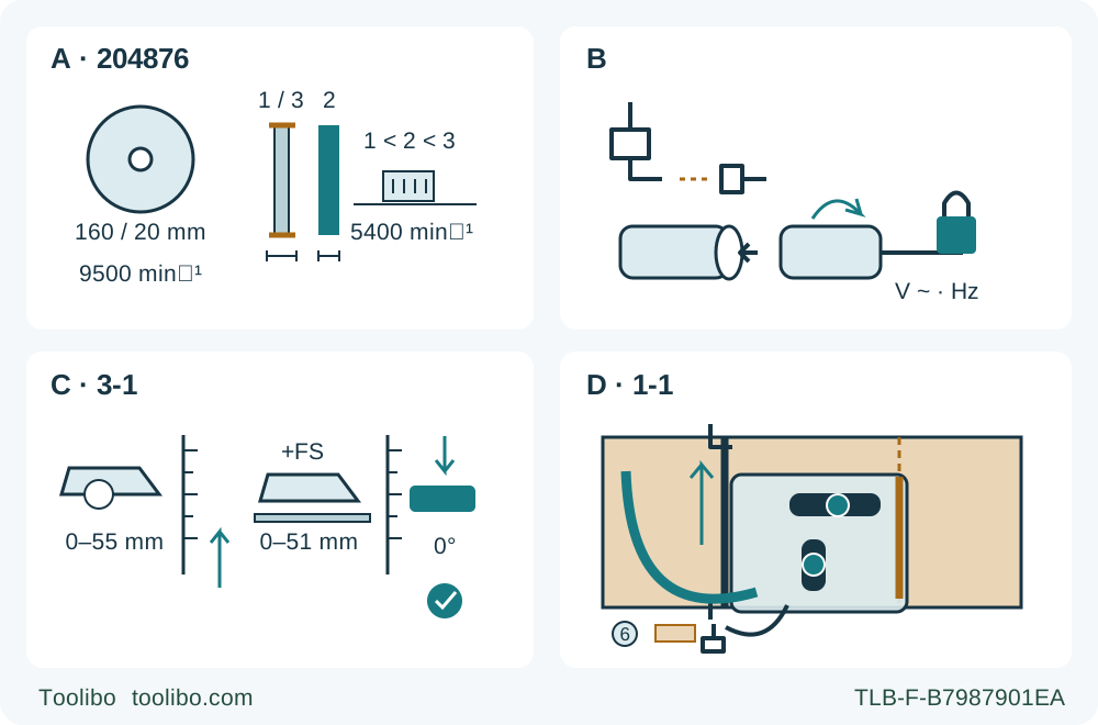
A · Confirm the existing matched assembly
The G manual requires the 160 mm / 20 mm EN 847-1 wood blade to be suitable for 9500 rpm. Preserve the correct core–wedge–tooth relationship; do not fit a thicker substitute from this diagram.
B · Isolate, then fully lock plug-it
Switch off before cable connection or disconnection and keep the supply unplugged during setup. The tool-side bayonet must be fully closed and locked.
C · Read the plain scale
Press depth adjuster 3-1 and use the no-rail reference. Set actual projection below the work to less than a full tooth and securely retain zero-degree adjustment.
D · Rehearse the supported travel
With supply disconnected, verify both grips, retained-side support, guide contact, hose and cord clearance through exit. The drawing supplies no factory guide-offset dimension.
All setup and the D rehearsal are disconnected. A labels 1 as blade core, 2 as guide wedge and 3 as tooth width; it is qualification, not a fitting procedure. B separates supply isolation from the fully locked tool-side bayonet. C shows alternative scale references, not a rail-mode switch; this task uses the plain scale and less than a full tooth below the wood. D is a conceptual stationary plan, not a running cut: upward travel, operator-right blade, retained base and guide left, two neutral grip contacts, clear hose and trailing disconnected cord. Speed 6 applies to the chosen solid wood.
The HK 55 EBQ combines an automatic pendulum guard, a guide wedge, a detachable plug-it cable and a depth scale with separate rail and no-rail references. A useful first task is to make those controls agree on one supported, square wood cut before treating the saw as part of a larger rail system. This workflow ends with an inspected sample and a repeatable setup; it does not commission an FS or FSK rail.
The exact scope is an existing HK 55 EBQ with T-Nr. 204876, matching manual 719373_G dated 2025-01-13 and the declaration’s specified serial range 40000000–49999999. Check the actual identity and complete supplied operating and safety instructions. This is a G-revision owner workflow; E-revision specifications are not transferred here, and the indexed manual is not claimed to be every owner’s latest supplied version. The actual nameplate determines voltage and frequency; do not import a North American supply specification into a European or UK machine.
Confirm the installed wood assembly before planning a cut
Use an already correctly fitted, undamaged original approved wood blade and its matched clamping parts. The G manual specifies 160 mm diameter and a 20 mm location hole, EN 847-1 compliance and a speed capability of 9500 rpm. That blade requirement is not replaced by the motor’s 2000–5400 rpm no-load range. A blade marked only for the motor’s maximum is not qualified by this guide.
The current document recommends a 1.8 mm cutting width and a 1.2 mm blade core. It permits a core range of 1.1–1.25 mm and a maximum cutting width of 2.2 mm with restricted guide-wedge function. Those figures are not a general invitation to choose any blade that fits the hole. For effective wedge operation, the blade core must be thinner than the guide wedge and the tooth width wider than the wedge. This workflow retains the original properly matched assembly rather than selecting a thicker alternative.
A bent guide wedge is a stop condition: even slight trouble can slow guard closing. Do not straighten it by eye or remove it to make a cut possible. Check for a damaged blade, uncertain clamping, housing cracks or stress whitening, and a faulty blade-change lever. Resolve any uncertainty through the complete matching instructions and appropriate service before use. There is no partial blade-removal, flange-fitting or torque procedure here.
Keep the machine disconnected for inspection and setup. Distinguish the blade-change lever from the pendulum-guard retractor and the separate plunge-function lever. Recognizing their locations is not permission to operate a service or plunge mechanism during an ordinary cut. For this edge-entry task the guard works automatically; it is not tied or held open.
Isolate the saw, then secure the plug-it connection correctly
The supplied, approved plug-it cable must be intact, with sound connectors and a supply matching the nameplate. Switch the machine off before connecting or disconnecting the cable. With the mains plug out of the supply, make the tool-side connection according to Figure 2 and fully close and lock its bayonet fitting. The manual warns that an incompletely locked connection can heat up and cause burns. Merely pushing the connector into place is not the complete check.
Keep the mains plug disconnected until setup and the stationary travel rehearsal are finished. A released trigger, a switch-on lock or an electronic stop is not a substitute for unplugging before work on the machine. Do not adapt a mismatched cable, repair a damaged connector or infer a regional plug design from an illustration.
The EBQ has an electronic brake, described as stopping the blade in approximately two seconds. That is not a timer for picking up the saw or touching the work. Actual standstill and guard coverage remain necessary. The EQ name on the shared manual cover does not make the EBQ brake claim transferable to an EQ body.
Current limiting can reduce speed under excessive load, and the motor resumes when the load is removed. Temperature protection can reduce power and restore full performance after cooling. Restart protection after a supply interruption is a different feature. None makes the machine physically isolated. If protection intervenes during this sample, stop, disconnect and resolve the cause under the full instructions rather than using repeated trigger cycling as a recovery method.
Set a zero-degree cut using the no-rail depth reference
Place the disconnected saw’s table on an even surface. Open the angle-setting knob, set the unit to zero degrees and close the knob securely. Check the indicated position and, without contacting sharp teeth, verify the intended square relationship using an appropriate square against the blade body. A failed check needs correction under the complete instructions; the factory end-stop adjustment belongs to the after-sales service procedure, not an improvised screw adjustment here.
Press the cutting-depth adjuster and raise or lower the saw using the main handle. Figure 3 shows the control and the split scale. Use the plain, no-rail reference for this task. The +FS marking is a separate depth reference for rail use, not a selector that turns a rail mode on. Do not read the rail side and then guess an additional allowance.
Set depth to suit the actual wood thickness, with less than a full tooth projecting below the work, and confirm the setting remains secure. The 55 mm no-rail maximum is a capacity, not the default depth for every board. Changing the material thickness requires a fresh depth check. This article does not use the rail maximum or teach bevel cutting.
With the plug still disconnected, check the pendulum guard using only its retractor lever. It must move freely, avoid the blade and other parts at all angles and depths of cut, and close promptly by itself when released. Keep fingers away from its sharp edges and return path. Slow, obstructed or incomplete closing rejects the saw for use until properly corrected.
Build the supported sample around the actual guide contact
Choose sound, dry, untreated solid wood with no hidden fasteners or unknown coating. Use a manageable piece that can be clamped to a stable platform. Do not hold it in a hand or across a leg. Support the retained piece and waste so the kerf will not close, the offcut will not drag the cut sideways and the saw’s base will not lose support at separation. On a larger panel, support both sides near the cut and near the edges while keeping every support clear of the actual blade path.
For a guided rip, clamp a straight edge securely and verify its contact with the actual base. The manual calls for a rip fence or straight-edge guide; this task uses the latter, not an unverified rail accessory. Mark the finished dimension and waste side, then establish the base-to-cut offset on scrap with the installed blade. Do not borrow an offset from another saw or a drawing.
The no-rail cut indicators distinguish zero degrees at Figure 7’s 7-1 from 45 degrees at 7-2. Use the zero-degree indicator as an aiming aid and confirm the real kerf with a sample. A mark is not a guarantee that every blade cuts exactly on the same side of a pencil line. There is no bevel or rail calibration outcome in this article.
Arrange extraction, personal protection and a clear travel path
The manual requires extraction and appropriate dust precautions. For this workflow connect a suitable Festool mobile extractor and an antistatic hose for the selected wood dust. The documented hose sizes are 27/32 mm or 36 mm, with 36 mm recommended to reduce clogging. The 27 mm adapter fits into the angle adapter; the 36 mm adapter fits over it. Verify the actual secure fit rather than forcing an unrelated connector.
The manual also describes a dust collection bag, but that does not make a bag equivalent to an extractor for every material or setting. This sample deliberately uses the connected extractor. No performance threshold from a different Bosch model is transferred here. Keep the hose clear of the guard, work supports, clamps and floor hazards throughout the entire cut.
Wear eye and hearing protection and appropriate respiratory protection; provide suitable ventilation. Set the speed wheel to 6 for the chosen solid wood, as specified in the material table. That setting does not authorize aluminium, plastic or mineral materials with different blades, dust controls or additional precautions.
While still disconnected, rehearse the whole travel with both original handles accessible and the base supported. Check entry, guide contact, exit, cord slack and hose movement. No clamp should obstruct the saw, and no hand should be needed to catch waste or rescue a snagging cable. Correct the setup before connecting power.
Make the edge-entry cut and accept the result
After all checks pass, connect to the correct supply with the switch released. Position the front of the table on the work with the blade clear of it. Hold both handles, keep the body to the side of the blade line and maintain a stable stance. Slide the switch-on lock upward, then press the on/off switch. Let the saw run up before advancing into the material.
Feed forward only, keeping the table flat and the guide contact controlled. Adapt feed to the wood without forcing the blade, twisting the saw or pulling it towards yourself. Stop using the machine if there is no soft start, speed cannot be controlled, smoke appears or there is a burning smell: the manual identifies these as possible electronic faults, not normal conditions to work through.
At normal completion, retain control, release the switch and wait for complete standstill. Confirm the automatic guard covers the blade before placing the tool down. If binding or an interruption occurs instead, release the switch and hold the saw motionless in the work until stopped; never pull a turning blade backward out of the kerf. Disconnect and determine the cause. This guide does not give an interrupted-cut restart or plunge sequence.
Unplug before measuring or changing the setup. Check the retained dimension at several points, straightness, squareness, edge quality and any sign of burning or guide movement. Also assess the process: guard travel, support through separation, cable and hose clearance, and any protective intervention. A dimensionally correct piece does not excuse a pinched blade or shifting support.
Correct any defect while isolated, then make another suitable sample before using valuable material. Keep cooling openings and the guard area clean under the complete maintenance instructions; never open the protective lid or motor housing as an owner shortcut. The accepted outcome is a stable no-rail square-cut setup with the G-revision controls understood, not a newly fitted blade or commissioned rail system.
Models referenced