
Four model-specific setup distinctions
A shows depth lever clockwise loosening and counterclockwise tightening with half-tooth projection; B shows the opposite bevel lever directions; C lowers the shoe, seats the dust port and returns to a locked cutting depth; D places kerf to the right of the indicator in waste.
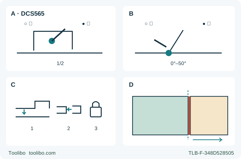
A · Set and lock the depth
Loosen rear lever 4 clockwise, set about half a tooth below the actual material and tighten counterclockwise. Verify the setting cannot shift.
B · Set and lock zero bevel
Loosen front lever 10 counterclockwise, set zero degrees and tighten clockwise; do not transfer the depth lever direction.
C · Complete the port installation
With battery removed, fully loosen depth, put the shoe lowest and push port 22 onto the body until its locks click. Restore and lock actual cutting depth before use.
D · Put the kerf in the waste
The indicator aligns with the left inner side of the blade; verify that the real kerf falls to its right into waste using a sample with the actual assembly.
Every setup panel assumes the battery is removed. Open circles mean loosen and filled circles mean tighten: A and B deliberately have opposite directions. A half-tooth is actual projection below the stock, within the less-than-full-tooth safety ceiling. B shows the mechanism range but this workflow uses zero degrees. C numbers mean shoe lowest, port locks engaged, then final depth restored and locked; it is not a running sequence. D is a kerf-allocation schematic only: its arrow points toward waste, not saw travel, and does not specify blade handedness.
A DCS565 owner can avoid several setup errors by treating the rear depth lever, front bevel lever and clip-in dust port as different mechanisms. Their locking directions are not interchangeable, and installing the port temporarily changes the shoe position. This workflow brings those details together in one supported, extracted, zero-degree wood sample, then checks both the piece and the process before repeating it.
The scope is a North American DCS565 matching the Type 1 manufacturer document N862094, dated 07/20, with its correctly installed original approved blade and an already commissioned genuine DCB205 battery and DCB107 charger system. The shared manual also names DCS566, but this article follows the DCS565’s identified components, worklight and hook. Match the actual labels and complete supplied instructions. This is an exact-document owner guide, not a claim that the 2020 manual is the latest version or that a current carton contains the named pair.
Start with identity, material and power-system boundaries
The manual calls the system 20V MAX; its footnote distinguishes the 18 V nominal voltage. That wording is not permission to fit a generic battery with a similar voltage label. The back-page compatibility table explicitly lists DCB205 and DCB107. For this task both must already have been qualified and used according to the actual complete system instructions. The battery should be ready and fully charged for the sample. If the owner has no matched charging instructions or the pairing is uncertain, resolve that before proceeding; this guide does not commission a charger or teach its indicators.
Do not use a damaged, modified, cracked, leaking or severely impacted battery or tool. Keep detached battery terminals away from metal objects, and keep the tool and battery out of wet conditions and excessive heat. The manual prohibits use or storage where temperature may reach or exceed 104 °F / 40 °C. An approximate battery fuel gauge indicates charge, not that the saw is functioning correctly or that the assembly is safe.
Choose dry, sound wood with no embedded fasteners, unknown coatings or concealed services beneath it. The intended-use section and blade warning expressly exclude metal, plastic, concrete, masonry and fibre cement. A blade-table entry mentioning vinyl siding does not override those prohibitions. This workflow stays wood-only and uses no abrasive wheel, pocket cut, overhead task or installed-panel blind cut.
Qualify the existing blade and automatic guard
Turn the tool off and remove the battery before inspection, adjustment, attachment work or cleaning. Keep the battery separate from the saw throughout setup. The trigger lock-off is a starting control, not physical isolation.
The manual specifies 6-1/2 in / 165 mm blades and requires the correct hole size and shape for the actual spindle. It also requires the blade’s maximum recommended speed to meet or exceed the saw’s speed. This article does not invent a bore or speed number from a different DCS body. Verify the actual original blade, machine markings, direction arrows and matched owner instructions. A label that cannot be checked, an uncertain washer stack or signs of damage are reasons to stop, not reasons to guess.
Keep the properly installed original blade and clamping assembly. The manual describes a left-hand-thread clamping screw, but recognizing that fact is not a complete blade-change procedure. Do not loosen it for this sample, add oil to the guard or clamp-washer area, or improvise a torque value. The manual specifically says not to lubricate that area. A blade requiring replacement or clamping correction needs the complete matched fitting procedure or qualified service first.
With the battery removed, use the guard-retracting lever to move the lower guard from fully closed to fully open, then release it. It must return fully, freely and promptly without intermittent movement, touching the blade or contacting other parts at all angles and depths of cut. A missing, damaged, misassembled, sluggish or obstructed guard rejects the saw for use until serviced. Never tie it open. For the ordinary edge-start cut below, the guard operates automatically.
Install the actual dust port before setting final depth
Use the proper DCS565 dust-extraction port and an appropriate dust extractor for the selected wood. The manual’s installation sequence starts by fully loosening the depth adjustment and putting the shoe in its lowest position. This is an attachment-access position, not the cutting depth for every piece of stock.
With the battery still out, fully loosen depth lever 4 and lower shoe 5 as shown in Figures H and I. Push port 22 onto the saw body until the locks engage with an audible click, then verify it is secure. Connect the appropriate matching hose without forcing an incompatible fitting. Do not substitute a guessed hose diameter or import another manufacturer’s installed-flow threshold.
After fitting the port, restore the shoe to the depth required by the actual work and lock it before use. Leaving the lever loose because the port is installed is an incomplete setup. Check that the port and hose do not obstruct the guard or either handle, and provide enough hose slack for the full guided travel without pulling the saw sideways.
Set depth and zero bevel with the correct lever directions
The rear depth lever and front bevel lever have opposite documented loosening directions. With the battery removed and the saw supported, loosen depth lever 4 clockwise, move the shoe to the required depth and retighten it counterclockwise. Do not force the lever in the familiar direction from another saw.
The efficient-cutting recommendation is to expose about half a tooth below the material. Figure K compares a piece of the actual stock against the blade to show the projection; the general safety ceiling is less than a full tooth. Set and check the real projection, avoiding sharp teeth, rather than using the maximum capacity as a default. The listed 54 mm zero-degree capacity does not require every board to be cut at that depth.
For the front bevel adjustment, loosen lever 10 counterclockwise, align the shoe and pointer with zero degrees, then tighten clockwise. The mechanism spans 0–50 degrees, but this task is square cutting only. Confirm the setting is secure and check the intended square relationship against the blade body with an appropriate square, without contacting teeth. If the result is wrong or the lock will not hold, stop and use the complete service instructions; do not adjust unidentified screws.
Recheck the guard after depth and angle changes. Then check both locks again. A locked angle does not prove the depth lock is secure, and a good guard test at one setting does not excuse interference at another.
Lay out the retained size, kerf and support
Mark the finished dimension and identify the waste side before setting a guide. The front kerf indicator lines up with the blade’s left, inner side, so the kerf falls to the right of the indicator. Guide the mark so that the material removed lies in the waste. Confirm this with the actual installed blade on scrap; do not centre the blade thickness on a finished-dimension line and then wonder why the piece is short.
For a guided rip, the safety instructions require a rip fence or straight-edge guide. This sample uses a securely clamped straightedge with an independently measured base-to-cut offset. The recommended DeWALT rip fence is not assumed to be in the owner’s carton, and no rail compatibility is inferred. Check the actual guide contact and clearance before tightening the guide clamps.
Secure the work to a stable platform. Support near the cut and, on a larger panel, on both sides near the line and near the outer edges. Keep all supports and fasteners out of the blade corridor. The wider portion of the shoe must remain over the solidly supported portion, not the piece that will fall away. Arrange the offcut so it cannot sag, rotate or pinch the kerf; do not plan to catch it by hand.
The manual recommends placing the more important appearance face down because cutting tends to splinter the upper face. Treat that as a starting choice, not a guarantee of finish quality for every wood. A sample still needs inspection. Thin waste strips must not become trapped in the guard, so avoid an awkwardly narrow first sample.
Rehearse while isolated, then make one ordinary edge-entry cut
Use the eye protection specified by the manual, ANSI Z87.1 (CAN/CSA Z94.3), and ANSI S12.6 (S3.19) hearing protection, with appropriate respiratory protection, ventilation and the dust extractor connected. Remove loose objects and keep bystanders clear. With the battery still out, check the complete path: both original handles accessible, shoe supported, guide clear, clamps outside the saw envelope and hose free through exit. No hand should be needed to hold the wood or move a hose while cutting.
After the setup passes, keep the switch off and fingers clear of the trigger while aligning the ready DCB205 with the handle rails. Slide it in until firmly seated and confirm it does not disengage. If it does not seat correctly, remove it and resolve the cause; do not hold a loose pack against the contacts while operating.
Hold main handle 20 and auxiliary handle 12, maintaining balance with the body away from the blade line. Place the front of the shoe on the work with the blade clear. Use the identified lock-off and trigger controls according to the matched owner instructions, and bring the blade to full speed before it contacts the wood. Never defeat or tape the starting controls.
Advance steadily forward with the shoe flat and the guide contact maintained. Do not force the saw through a knot, twist it to chase a drifting line or change hand position mid-cut. If the cut goes off line, release the trigger and allow complete standstill before withdrawing or repositioning. The sample can be rejected; saving a pencil line does not justify steering a rotating blade sideways.
At normal completion, release the trigger and let the blade stop before lifting the saw from the work. Confirm the spring-loaded lower guard closes over the blade before placing the saw down. No brake time is assumed here. If binding or a stall occurs, follow the general safety requirement to release the trigger and hold the saw motionless until complete stop. The shorter stall sentence elsewhere in the manual does not authorize withdrawing a moving blade. Remove the battery and investigate; this guide gives no abbreviated jam-restart procedure.
Accept the sample and store the isolated tool
The DCS565 worklight remains on for about 20 seconds after trigger release. That delay is not a blade-motion indicator, and the light is not intended as a flashlight. Do not wait for darkness instead of checking actual standstill, and do not reactivate the trigger merely to inspect the cut.
Remove the battery before measuring, adjusting or clearing waste. Check retained width at several points, straightness, squareness, splintering and burning. Also check whether the guide shifted, the offcut moved, the guard hesitated or the hose snagged. A visually clean edge does not validate a setup that bound or lost support. Correct problems while isolated and repeat on suitable scrap before committing valuable stock.
The rafter hook is not a body tether, an overhead suspension point or a hanger for another load. This workflow uses a stable resting surface, not elevated hanging. Keep the tool and detached battery secure against falling and protect the battery terminals.
For nonmetal parts, the manual allows a cloth dampened with water and mild soap, not harsh solvents; keep liquid out and never immerse the tool. Battery cleaning has its own dry-cloth or soft nonmetallic-brush guidance. Do not mix those methods or lubricate the guard/clamp area. Repairs and unresolved guard or adjustment faults belong with the specified qualified service. The finished result is a verified Type 1 wood-cutting setup with the correct locks, port and kerf allowance—not a newly commissioned charger or replacement blade system.
Models referenced