
Four qualifications before a rail-free wood sample
A shows plate at most 1.6 mm, knife 1.7 mm, kerf at least 1.8 mm and two separate 2–3 mm gaps. B pairs a detached DCB606 with partial-tooth projection and depth 8. C identifies both bevel locks 7, grips 11 and 3, start 1 then 2 and rail-free mark 27 rather than 29. D shows zero rotation before covered safe setdown.
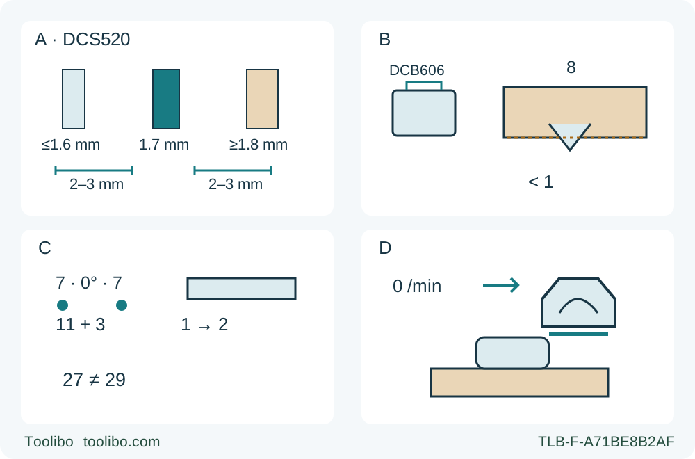
A · Retain the qualified original assembly
165/20 mm blade rated at least 6000 rpm; plate at most 1.6 mm, knife 1.7 mm, kerf at least 1.8 mm and both 2–3 mm clearances. Unknown assembly holds the task.
B · Remove the pack and verify actual depth
With DCB606 removed, secure depth 8 and confirm a through-cut with less than one full tooth below the stock. The about 3 mm note cannot override that limit.
C · Separate controls and references
Secure both zero-bevel knobs 7; use grips 11/3, start 1 forward then 2, and rail-free cutting indicator 27. Position indicator 29 is not the square alignment mark.
D · Observe actual stop and coverage
Release after normal complete exit, wait for standstill before moving away, verify sprung guard enclosure and set down on the side safely; remove battery for acceptance.
Conceptual qualification diagram, not a fitting procedure or live operating pose. A requires both existing knife gaps. B is not a scale drawing or a universal 3 mm setting: actual through-cut and less-than-full-tooth projection must coexist. C groups identifiers, not their physical locations, and does not authorize interior plunge or rail setup. D means actual complete stop and sprung guard coverage before safe on-side setdown; remove the pack for inspection. Binding/interruption instead requires motionless hold until stopped.
A DCS520 can have a correctly charged battery and still be an unqualified cutting system. Its original blade must work with its riving knife; the sprung guard must return freely; the depth must suit the actual stock; and extraction must be operating, not merely attached. This guide joins those checks into one rail-free, zero-bevel edge-entry crosscut in clean loose solid wood. The result is an inspected sample and a recorded decision about further work, not a commissioned track system.
1. Match the Canadian Type 1 system
Use this workflow only for an actual DCS520 Type 1 matching the Canadian product’s N486591 FEB17 instructions and familiar physical controls. Read the complete supplied saw, battery, charger and extractor instructions first. The Canadian download identifies Type 1; a similar housing, a different country’s page or a kit suffix does not establish the same instructions. If the actual identity or control behavior is uncertain, stop for qualified identification.
The manual specifies a 165 mm blade with a 20 mm bore, rated for at least 6000 rpm. Its supplied combination blade is intended for general ripping and crosscutting. This workflow retains that correctly installed, identified original wood assembly; it does not authorize a substitute blade or teach fitting. The original knife is 1.7 mm thick, with blade plate at most 1.6 mm and kerf at least 1.8 mm. The plate must be thinner than the knife and the kerf wider. Both distinct clearances shown in Figure E must already be correctly established at 2–3 mm. One measured gap does not establish the other. A bent knife, uncertain assembly, incorrect mounting parts or unknown clearance requires qualified correction before operation, not a trial cut.
Do not transfer DWS520 knife dimensions to this cordless model. Nor should product capacities be turned into depth settings: the current product gives on-track figures of 54 mm at 90° and 41 mm at 45°, while this manual gives 55 mm with a rail and 59 mm without. These are retained source differences, not a combined capacity promise. The small sample must fit the actual qualified setup comfortably. This guide includes no rail installation, splinter-strip trimming, internal plunge, door trimming, angled cut, nonwood cutting or anti-kickback reset.
2. Isolate, then inspect the complete tool
Release the switch and wait for complete blade standstill. Press battery release 15 and remove pack 14 before inspection, settings or attachment work. A released trigger, lock or charge display is not physical isolation. Protect your eyes during inspection as well as cutting; the manual specifies ANSI Z87.1, with CAN/CSA Z94.3 also identified in its safety guidance. Keep fingers clear of teeth and do not defeat the guard to obtain a measurement.
Before each use, check free guard movement and immediate blade enclosure, its return spring, and clearance from the blade and other parts at all angles and depths of cut under the complete instructions. A drop can bend the guard, but the check is not reserved for dropped tools. This is a plunge-head guard system, not a pendulum guard to be held open with an invented external lever. Slow return, contact, damage or an uncertain check means service before use.
Inspect the accessible original blade and mounting condition: the blade must be clean, sharp and undamaged, with no loose or incorrect parts. Check the shoe, handles, locks and switch for damage, binding or abnormal movement. Verify that the switch operates properly and returns to OFF; a switch that cannot reliably control the tool is a service hold. Do not energize a suspect tool to reproduce a fault, change its blade here, sharpen it or try a chemical cleaning recipe. Remove setup keys before reconnection.
3. Qualify power and dust control separately
The narrow power scope is an actual DCB606 battery and DCB118 charger already correctly commissioned under their complete matched instructions. The manual’s final table explicitly includes that pair. It is not a carton-content promise, a charging tutorial or permission to substitute any battery displaying the same brand. Its 60 V MAX marking describes maximum initial voltage; the stated nominal voltage is 54 V. Neither number establishes compatibility with other regional equipment.
A battery or charger that has been dropped, received a sharp blow or been damaged requires the manual’s service route, even if its exterior appears usable. Do not use or store the tool and pack where temperatures may reach or exceed 104°F/40°C. A pack’s fuel gauge indicates charge, not that the saw is sound. Use an appropriately charged, qualified pack; unresolved power-system instructions or condition hold the task.
The saw must be connected to an actual dust extractor designed in accordance with the relevant dust-emission regulations. Establish that from the extractor’s own documentation and the actual material, not a generic vacuum label. The manual identifies a 1-1/4 in hose connection and requires a tight fit; it warns of static charge without an antistatic suction hose. Confirm the actual hose and coupling are suitable and remain secure through the whole movement. Do not insert objects into the exhaust or aim dust at people. Start and operate the qualified extractor under its instructions before cutting, and verify its intended operation. A connected but inactive hose is not adequate extraction.
Use the specified eye protection, ANSI S12.6 hearing protection and appropriate approved respiratory protection for the dust, with ventilation and bystanders kept clear. Extraction does not eliminate those duties. Do not wear fingered or loose-fitting gloves during use. There is no imported pressure/flow threshold, universal adapter approval or guaranteed collection percentage in this workflow.
4. Lay out an edge-entry sample that can finish safely
Choose clean, dry, known solid wood suitable for the retained combination blade. Work in a dry workplace, never in wet conditions or where flammable liquids or gases are present. Inspect the entire proposed route and underside for nails, wire or other foreign material; reject uncertain stock. Mark the wanted side, waste and square line from a trustworthy reference edge. Put the appearance face down as directed for optimum results, without expecting both faces to be splinter-free.
Clamp the retained work to a stable platform. Support retained stock and separating waste independently, near the cut and edges where needed, while keeping every support outside the blade and knife path. The waste must separate without falling dangerously, closing the kerf or being trapped by a clamp across it. Never support it with a hand. The shoe needs adequate bearing at entry, along the route and through a clear exit; no minimum offcut size or overhang is invented here.
With the battery removed, assess reach, footing, clamp locations and hose slack beside or safely above the route, with the blade guarded and no tooth contact. Do not push a projected blade through uncut stock as a rehearsal. Both hands must remain on their designated grips without leaning into the blade line. If actual support, exit or return clearance cannot be established, choose a different qualified setup or stop; do not shorten the board into a loose hand-held recut.
5. Set actual depth, zero bevel and the correct reference
With the pack removed, loosen both bevel adjustment knobs 7, set the actual zero-bevel position and secure both. Loosen depth knob 8, move the pointer on scale 9 to the needed cut depth and tighten it. Verify the actual setup, not merely a printed scale number: the blade must cut through the stock while less than one full tooth projects below it, with unobstructed underside clearance. The manual’s approximately 3 mm projection note describes optimum results; it does not override that safety limit. If through-cut and tooth exposure cannot both be satisfied, hold the task.
For this solid-wood sample, wheel 19 has the documented solid-wood range 3–7. Establish an appropriate familiar setting while isolated under the complete instructions; do not invent an rpm for each number or use the table’s other materials to widen this wood-only task. The manual gives the overall 2500–4200 rpm range, not a promise of loaded speed.
Identify rail-free cutting indicator 27 for the square line. Indicator 29 instead denotes blade position at full plunge; it is not a substitute alignment mark for this sample. No guessed rail offset is added. Any auxiliary straight guide would require its own actual clearance and calibrated contact-side qualification; it is not a track system. Keep this first manageable sample within your established ability to follow the marked line without twisting or forcing the saw.
6. Make the normal cut, then inspect while isolated
Confirm OFF, clear controls and the completed setup before inserting the qualified pack. Align it with the handle rails, slide it firmly into place and ensure that it is securely seated and cannot disengage. Keep hands out of the cutting area and from under the work. Grip front handle 11 and main handle 3 securely, using insulated gripping surfaces, and stand to either side of the blade rather than in its line.
Place the front of shoe 4 on the supported retained work with the blade clear. Push plunge trigger 1 forward, then press the on/off switch 2. Let the blade reach full speed before contact, lower under control to the set depth and push forward along the line. Maintain both grips and shoe support; do not pull the machine backward toward you, twist to chase the line or force a struggling blade. The original knife must engage the work to function; it is ineffective during short cuts and is not immunity from kickback.
For a normal complete cut, finish the planned clear exit, release the switch and wait for complete blade standstill before lifting or moving the saw away. Confirm sprung guard enclosure before placing the tool on its side on a stable surface where it cannot trip anyone or fall. Remove the battery before inspection. Do not infer a stopping time or use a brake expectation instead of observing actual standstill.
Binding or interruption is a different route: release the trigger and hold the saw motionless in the material until the blade stops. Never pull a moving blade backward or lift it out of a trapped kerf. Isolate when safely possible and obtain qualified assessment of the cause. This guide does not teach trapped-tool extraction, old-kerf restarting or operation of the rail anti-kickback knob.
Check complete separation, measured length, squareness through the thickness, both faces and the cut edge. Record tearout, burning, taper, unexpected drag, movement or loss of extraction. An unacceptable result does not justify repeated powered experiments or a small loose-piece correction. Resolve its cause under the complete instructions or seek service; only a sound, qualified system and an acceptable sample support planning the next ordinary cut. Store the isolated tool dry and secure, maintain its instructions and refer repairs to the specified authorized service route.
Models referenced