
CMCS551 Type 3 isolated checkpoints
Four panels show original 184 mm blade qualification at 6000 rpm or higher, a detached battery, separate depth 13 and bevel 9/10 controls, and dust port 18 connected to an extractor.
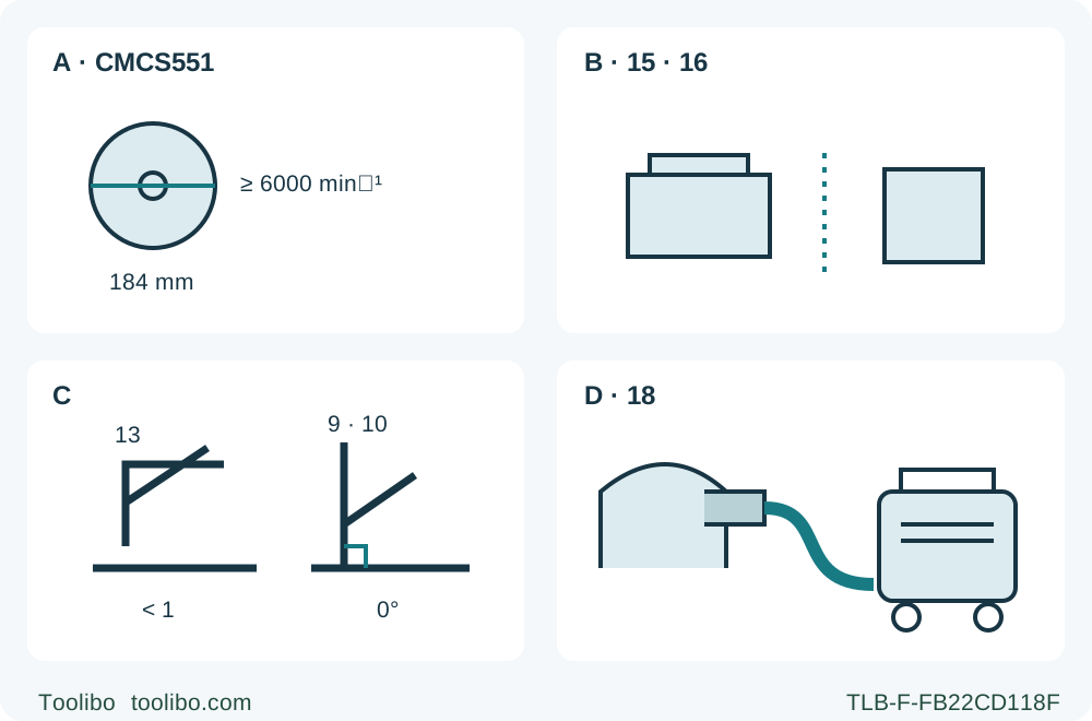
A · Exact original assembly
Match physical Type 3 and NA701538 03/25, retaining the approved original 184 mm wood blade rated at least 6000 rpm and native mounting assembly.
B · Remove power
Release the switch, wait for complete standstill, press release 16 and withdraw battery 15 fully before checks or adjustments.
C · Secure both settings
With the battery removed, set and lock depth 13 to less than a full tooth; set zero using bevel lever 9 and scale 10, then verify the actual sample.
D · Complete extraction
Verify existing approved port 18, suitable compliant vacuum and full-route hose clearance. Always wear the required approved dust mask; connection alone is not compliance.
All setup panels refer to a removed battery. A is original-assembly qualification, not fitting. C separates the depth lever from the zero-bevel lock without asserting operating handedness. D requires an already complete approved port and suitable documented compliant extractor; no numerical performance or retrofit specification is implied.
This is an existing-owner workflow for a physical US CRAFTSMAN CMCS551 Type 3 that matches manual NA701538, dated 03/25. The current CMCS551B product page offers several manual versions; choosing the newest-looking link does not establish applicability to an older tool. Check the actual type and supplied documentation before using these controls. The B bare-tool suffix is not a second saw body or a promise that a battery and charger were included.
The complete outcome is a supported, square, ordinary edge-entry wood sample with the original qualified assembly, an already commissioned power system and the required complete extraction setup. It is not a track-conversion, charging, blade-fitting or brake-test tutorial. A missing prerequisite means hold rather than substituting another CRAFTSMAN manual.
Confirm the Type 3 assembly and actual power documents
Require the already correctly installed original, manufacturer-approved wood blade and native mounting parts, clean, sharp, undamaged and with known service history. The Type 3 blade-selection section specifies 7-1/4 in / 184 mm diameter, 5/8 in / 15.9 mm bore and a blade rating of 6000 rpm or higher. The tool’s separate 5000 rpm no-load figure does not reduce that blade requirement. Abrasive and dry diamond wheels are excluded.
Figure C shows a specific inner washer, O-ring, blade, outer washer and bolt arrangement. This guide neither dismantles it nor turns recognition of those parts into an abbreviated fitting sequence. Uncertain washers, a missing part, an unidentified blade or evidence of modification require the complete exact instructions and qualified correction. A related product link or current 24-tooth package description does not by itself approve a replacement blade for the owner’s assembly.
The manual requires the battery and charger instructions supplied in the original tool manual or a separate Batteries and Chargers manual. Have those complete documents for the actual already commissioned pair. Its footer lists battery packs CMCB201, CMCB202, CMCB204, CMCB2015, CMCB205, CMCB206 and CMCB2011, and chargers CMCB100, CMCB101, CMCB102, CMCB104, CMCB1104 and CMCB124. Check both actual labels and the established applicable pairing; a V20 logo alone is not sufficient evidence.
This workflow does not commission a new combination or teach charging. The recommendation to use a 4 Ah or larger pack for best results is not an absolute minimum that invalidates every smaller listed pack. The documented 20 V Max description refers to maximum initial no-load voltage; nominal voltage is 18 V. Neither statement authorizes a different system, an adapter or a damaged pack. Do not use damaged or modified batteries or attempt to service them.
Isolate the tool and verify the guard
Release the on/off switch, wait for complete blade standstill, press battery-release button 16 and withdraw battery 15 fully from the handle. Keep the detached pack protected under its own instructions, with terminals away from loose metal. The removal paragraph’s reference to inserting a pack in a charger is not an instruction to charge during every inspection; charging remains outside this owner task.
With the pack removed, use retracting lever 8 to check that lower guard 7 moves freely and closes instantly when released. It must not contact the blade or another part at any angle or depth of cut. Check the spring and actual assembly condition as well. A missing, damaged, misassembled or slow guard means no use until corrected by the appropriate qualified service. Do not hold it open during this ordinary edge-entry cut or use a powered trial to prove a doubtful guard works.
Inspect the main and secondary handles, switches, shoe and adjustment locks for damage and secure condition. Unknown behavior is not diagnosed by repeatedly starting the saw. The work light is illumination, not proof that power is isolated or that an automatic restart cannot occur. Remove the battery for all setting changes, clearing and inspection regardless of what the light shows.
Make extraction and personal protection real prerequisites
For wood sawing, this Type 3 manual requires a vacuum extractor designed in compliance with the applicable dust-emission directives and always requires an approved dust mask. Verify suitability from the actual extractor’s documents and follow its instructions. Merely fitting a hose to an opening does not prove compliant dust control, and this source gives no universal numerical airflow threshold to borrow from another model.
Require the already correctly fitted complete approved dust-port 18 assembly. The manual describes the port as an extra-cost accessory, while the current product describes a vacuum adapter accepting 1-1/4 in hoses. Those statements do not guarantee that an owner’s tool has the complete parts. If the port, fastening or applicable assembly instructions are missing, stop and resolve them rather than inventing a retrofit. Connect the actual suitable hose, check airflow and collection readiness, and ensure it can move through the full route without dragging the saw or catching a guard or clamp.
Wear ANSI Z87.1 eye protection (CAN/CSA Z94.3), ANSI S12.6 (S3.19) hearing protection and appropriate approved respiratory protection for the dust, with ventilation and bystander exclusion. Ordinary glasses are not safety glasses. The circular-saw instructions explicitly prohibit loose-fitting gloves or gloves with fingers during operation; do not import a general “wear work gloves for everything” rule from another tool. Keep clothing, hair and jewelry away from moving parts and retain both designated grips.
Set the actual depth and zero bevel
Keep the battery removed. Loosen depth lever 13 to unlock shoe 5, align the shoe with the intended markings on the depth strap, and tighten the lever to lock the setting. Confirm actual tooth exposure beneath the board. The adjustment page and Figure I describe one tooth, but the general cutting rule requires less than a full tooth. Use the stricter actual less-than-one-tooth setup here, not a factory-mark assumption. Check the whole underside path for clearance from supports and the bench.
For the square cut, loosen bevel lever 9 counterclockwise, position the shoe at zero on bevel scale 10 and tighten the lever clockwise. Verify secure locking. The manual’s wider angle range does not turn this into a high-angle exercise. Its calibration screw 21 is not an ordinary setup control in this workflow. If a locked zero setup does not yield a square sample, use the full correction instructions or qualified service rather than adjusting a screw experimentally.
The original blade and actual material thickness must fit the documented capability without forcing a marginal setup. The manual lists 65 mm at zero, but a maximum specification is not a suitable first-sample target or an allowance to remove a guard. Select modest, manageable stock with room to maintain the shoe, guide and hose relationship throughout.
Plan a supported edge-entry route, not a track shortcut
Use known, dry, untreated, nail-free loose wood and inspect the entire route for wire, fasteners or other foreign material. The intended-use section excludes metal, masonry, glass, tile and plastic. Avoid wet conditions, sap-coated problem stock and unknown coatings for this qualification sample. Do not use a dull blade to see whether a slower feed makes the task acceptable.
Mark the wanted dimension and waste side. Secure the retained work to a stable platform; support both portions independently near the cut and edges with supports outside the blade path. Keep the broad shoe on supported retained work. Waste must separate without sagging or twisting into a closing kerf. Do not hold the board on a leg, catch the offcut or arrange a long panel only on distant end supports.
For ripping, use a suitable straightedge guide or an already qualified prescribed fence, as required by the cutting safety rules. This task uses a clamped straightedge and verifies its actual blade-to-shoe contact offset on scrap; it does not teach partial installation of the optional fence. Keep guide and clamps clear of the moving tool and hose. The product’s track-compatible description and manual rail cross-section are not permission to put this setup on an arbitrary track. Track commissioning, shoe conversion and rail instructions remain outside this task.
With the battery removed and blade guarded, assess entry, middle and exit reach beside or safely above the proposed path without tooth contact. Confirm two-hand control, footing, continuous base support and hose freedom. If completing the cut requires reaching across the blade line, shifting supports or managing the hose with one hand, rearrange before proceeding. Choose which face may tolerate splintering and verify the actual finish on the sample; no stacked backer is introduced here.
Cut once, stop fully and accept the result
After every isolated prerequisite passes, confirm the switch is released. Align the qualified battery with the handle rails, slide it in until firmly seated and check that it does not disengage. Hold main handle 3 and secondary handle 4 with both hands, body beside the blade line and arms positioned to resist a sudden reaction. Put the shoe on supported work with the blade clear of the material.
Press lock-off button 2 from either side and hold it while depressing on/off switch 1. Once running, release the lock-off while holding the switch. Reach full speed and let the blade run freely for a few seconds before entering, as the manual directs, then advance with gentle continuous pressure and the shoe pressed flat against the work. There is no lock-on provision; never tie the switch or force the tool to correct a missed line.
If the blade binds or the cut is interrupted, release the switch and hold the saw motionless until the blade stops. Never pull a moving blade backward through the kerf. Remove the battery before investigating; this guide supplies no interrupted-kerf restart or shutdown-reset procedure. At normal completion, release the switch, wait for complete standstill before withdrawing, and verify lower-guard coverage. Place the tool on its side on a stable surface without a trip or fall hazard, then remove the pack before measurement.
The manual describes an automatic electric brake stopping the blade within one to two seconds. That is a manufacturer description, not a countdown permitting removal or setdown. Actual standstill and guard coverage govern every time. Unexpected stopping or control behavior is a hold for the complete instructions and qualified service, not repeated energized brake testing.
Accept the sample only when its dimension, straightness, square cut and face finish meet the planned result and the process also passed: settings stayed locked, guide did not shift, shoe remained supported, hose stayed clear and waste separated freely. Preserve the actual blade, power-document, depth and guide record. A correct dimension cannot excuse a guard defect, poor dust control or loss of support.
Leave the system in a controlled condition
Remove the battery for storage and care, protect its terminals and keep tool and pack away from children and untrained users. The footer prohibits storage or use where the environment may reach or exceed 40°C; do not leave the system in a hot location simply because it is switched off. Charging temperature instructions belong to the complete actual power-system documents, not a guessed hot-pack remedy.
Cleaning and repairs must follow the complete manual and its service boundaries. Do not improvise solvents, compressed-air techniques, battery opening or brush work from a short owner article. Keep the actual Type 3 identification and acceptance record with the tool. This completed square-cut setup does not transfer to Type 1 or Type 2, prove a replacement assembly, or authorize a new charger, rail or protective-function test.
Models referenced