
Four qualifications for the plain PKS 55
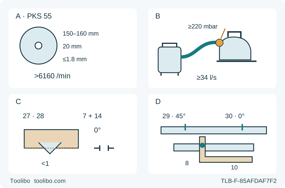
A identifies the original approved blade dimensions and conservative above-6160-rpm gate. B shows a hose between extractor and saw, with required 220 mbar and 34 l/s highlighted at the tool connection. C separates depth lever 27 from both zero-bevel bolts 7 and 14. D distinguishes native 0-degree mark 30, 45-degree mark 29 and parallel guide 10 with lock 8.
A · Establish actual blade approval
Original qualified wood blade: 150–160 mm diameter, 20 mm bore, plate at most 1.8 mm and EN 847-1. Verify rating above 6160 rpm under the conservative conflict gate; unknowns stop the task.
B · Verify performance at the tool
Actual installed extractor must provide at least 220 mbar AND 34 l/s at the saw connection, with suitable filtration, actual compatible hose path and active operation.
C · Isolate and secure the settings
Unplug, set actual through-cut with less than a full tooth exposed using lever 27, and secure both bevel bolts 7/14 at zero.
D · Use the plain-model guide reference
Unplug before fitting the actual guide 10 through the base, setting width at native zero mark 30 and securing bolt 8. Confirm full support/clearance and measure the sample.
Conceptual qualifications, not a fitting or live cutting pose. A does not identify a supplied blade: actual manufacturer approval and rating remain mandatory, and above 6160 rpm is an editorial gate addressing the product/manual conflict. B locates BOTH required operating values at the tool end, not the vacuum outlet or free-air headline; actual Fig B connections must qualify. C requires unplugging and actual less-than-full-tooth depth. D represents the plain model’s native marks and parallel guide, not CutControl or a rail; actual sample measurement confirms width.
The plain UK PKS 55 is not the PKS 55 A or PKS 66 AF pictured in much of its shared manual. It uses native cut marks rather than a fold-out CutControl window, and its model table does not include the dust/chip box. This owner workflow therefore uses the actual parallel guide against a known straight wood edge and an already qualified external extractor. The finished outcome is one measured, square-edged sample strip, with its width and process checked before any larger job.
1. Close identity and blade approval before planning a cut
Match the actual plain PKS 55 to UK order 0603500070, physical type 3 603 E00 070 and the supplied instructions. The current linked operating document is 1 609 92A F5R, dated 22.05.2026. Read it in full with the actual extractor instructions. The accompanying F6Z UK declaration identifies the body and date; it is not this article’s independent compliance certificate or approval to pool the 071 variant. A different suffix or region needs its own qualification.
The retained original wood blade must be correctly fitted, identified, sharp, clean and undamaged, with exact manufacturer approval for the saw, material and task. The manual specifies diameter 150–160 mm, 20 mm bore, base-blade thickness no greater than 1.8 mm, and blades tested and marked to EN 847-1. Dimensions alone do not prove suitability. The current product delivery list does not identify a factory blade part, so do not infer one from a photograph or assume every blade still on an old saw is original.
There is a speed discrepancy that must remain visible: the manual lists 5600/min, while the current product page gives 5040–6160 rpm. The manual requires the blade’s permitted speed to be higher than the tool’s no-load speed. This workflow applies the deliberately stricter editorial gate of a verified blade rating ABOVE 6160 rpm, together with actual manufacturer approval. That is not a correction to the manufacturer’s 5600 figure, a new speed setting or proof that every supplied blade qualifies. If approval or the actual blade rating cannot be established, stop for qualified confirmation before cutting. Do not install a different blade using a partial recipe from this article.
The original washers, flanges, bolt and orientation must also be correct. Unknown, loose, damaged or mismatched hardware means service or complete qualified correction, not a test cut. No fitting torque, flange conversion, grinding wheel, HSS blade or metal-cutting procedure is included. Other published differences—4.000 kg versus 3.9 kg without the cable, duplicate 1200 W input/output fields, and different noise-test standard references—are not grounds for efficiency, performance or exposure claims.
2. Inspect unplugged and qualify the actual supply
Release the trigger, wait for complete blade standstill and unplug before settings, inspection or attachment work. Check the cord, plug, handles, shoe, locks, original blade and accessible mounting condition. The switch must move freely and return to OFF. Damage, binding, misalignment, an unreliable switch or unexplained looseness requires correction before use; do not connect power to reproduce a fault.
Before each use, operate the lower guard with its actual retracting handle under the complete instructions and verify free movement, immediate closure and no contact with blade or other parts at all angles and depths of cut. Check the spring as well. A drop can bend the guard, but full-range clearance is a normal pre-use obligation. Keep fingers clear of teeth. Never tie the guard open; sluggish return or interference requires service. For the ordinary edge-entry cut below, the guard operates automatically, not held open by hand.
Use the existing correct, undamaged GB fused plug and a supply matching the actual nameplate. The manual’s 230 V table reference is not a universal voltage claim. Incompatible sockets, damaged cable or uncertain supply must be resolved by the specified authorized service or appropriately qualified supply professional. This guide provides no plug cutting, fuse replacement, extension sizing or impedance-measurement instructions. The manual warns of turn-on voltage transients; the separate 0.34-ohm conditional-connection paragraph is expressly for PKS 66 models, not a borrowed PKS 55 procedure.
Keep the workplace dry, well lit, well ventilated and free of flammable or explosive hazards, with bystanders clear and stable footing. Wear eye and hearing protection and suitable breathing protection. Keep hair, loose clothing and jewelry away from moving parts. Remove the setup key before connection and do not carry the saw with a finger on the trigger.
3. Prove extraction at the tool connection
This is a hard prerequisite, not an optional cleanup preference. F5R requires at least 220 mbar vacuum pressure AND at least 34 l/s flow, equivalent to 122.4 m³/h, at the power tool’s dust-extractor connection. Establish both values for the actual installed operating system under the applicable equipment instructions. A vacuum’s maximum sealed-pressure figure and separate free-air flow headline do not establish those two operating values at the saw. If that evidence is unavailable, hold the cutting task for a qualified extraction solution.
The manual recommends a 35 mm nominal hose and dust class M filtration. Neither recommendation guarantees the installed pressure and flow. The extractor and filtration must suit the actual material; especially harmful or carcinogenic dry dust requires a special extractor. Suitable breathing protection and ventilation remain necessary, and material-specific rules still apply. If suction decreases, stop work and eliminate the cause safely before resuming.
With the saw unplugged, use the actual manufacturer-qualified connection corresponding to Figure B: the hose 23, native chip-deflection tube 24 where applicable, and chip ejector 16 must form the intended secure path. Follow the actual equipment’s attachment instructions. Do not declare tube 24 equivalent to a different appendix adapter, force an arbitrary hose onto the port, or assume a shared accessory picture qualifies every vacuum. The appendix’s HEPA marking alone does not establish dust class M or installed performance.
Connect the other hose end to the qualified extractor, arrange slack and clearance, and operate/check the extractor under its own instructions before the sample. Do not assume an automatic-start socket is compatible merely because the manual describes one. The plain PKS 55 does not gain the A/AF dust box by sharing a manual, so that alternative is not used here. Hands must stay out of the chip ejector as well as away from the blade.
4. Establish a real straight-edge and support plan
Select known clean, dry, untreated loose wood suitable for the identified original blade and a cut with the grain. Inspect the entire intended route and underside for nails, wire, stones and other foreign objects; reject unknown material. The edge followed by the parallel guide must actually be straight and sound. A wavy reference edge will reproduce a wavy result, and guide pressure cannot repair it.
Choose a manageable sample large enough for the actual shoe, guide and clamps throughout entry, travel and exit. Mark the wanted strip, waste side and intended width from the reference edge. Do not begin with a tiny offcut or assume a universal minimum width. Secure the retained work to stable support. Independently support the separating portion without trapping it across the kerf, allowing it to separate without dangerous falling or closing onto the blade. Supports must be near enough to prevent sag but completely outside the cutting path. Never hold the stock on a leg or support the waste by hand.
Unplugged, with the blade guarded and no tooth contact, check reach and clearances beside or safely above the full route. The broad shoe bearing, actual guide contact, guard sweep, underside blade clearance, clamp positions, two-hand reach, cord and hose must all remain viable. Include the final exit rather than judging only the starting position. Do not push an exposed blade through uncut wood as a rehearsal. If any section requires moving a clamp during a cut, losing guide contact, leaning into the blade line or making a loose-piece recut, redesign the qualified setup or obtain suitable precut stock instead.
5. Set depth, both bevel locks and the native guide reference
Keep the plug removed. Loosen depth lever 27; pull the saw away from base plate 12 for a shallower cut, or move it toward the base for a deeper cut. Set the required depth on scale 28 and secure the lever. Verify actual through-cut with less than one full tooth visible below the wood and clear space underneath. Do not rely only on a nominal scale number or import another model’s up/down lever-unlock direction.
Loosen both bevel wing bolts 7 and 14, bring the actual scale 5 to zero and retighten both. Confirm neither setting can shift. This sample has a square blade and does not teach a bevel cut or calibration. An unexplained zero or depth error is a hold, not a powered adjustment experiment.
Use the plain PKS 55’s native 0° mark 30 for this task; mark 29 is for 45°. There is no CutControl window 9 to fold out. Loosen guide wing bolt 8, slide the actual parallel guide 10 through its guide in base plate 12, set the intended width against the corresponding zero mark 30 and retighten bolt 8. Confirm the fence sits against the qualified straight reference edge without forcing the saw sideways and that shoe and guide remain supported through the planned route.
The blade determines the actual kerf. Treat the guide scale as an initial setting to be verified by this same-material sample, not a guaranteed finished width or a universal contact-side offset. A physical guide can be suitable yet still need a measured result check. No plastic rail joining, first lip cut or rail-based support is authorized by this parallel-guide task.
6. Cut under control, then accept or hold
Before plugging in, confirm OFF, all locks secure, setup key removed, path clear and active extraction qualified. Hold insulated main grip 17 and auxiliary grip 3, with your body beside rather than in line with the blade. Keep both hands away from the cutting area, underside and chip ejector. Rest the front of the base firmly on the supported retained wood with the blade clear of the edge.
First press lock-off 1, then press and HOLD trigger 2. The trigger cannot be locked on and must remain pressed throughout operation. Start clear of the wood, allow steady running speed before contact and feed forward evenly, maintaining guide contact and full shoe support. Let the lower guard operate automatically. Do not force the saw, twist to chase the line or increase pressure to overcome a speed drop. Long spiral chips from some softwood rips can block the ejector; reduced extraction is a stop condition, not an invitation to reach into it.
After normal complete separation and clear exit, release trigger 2. Wait for actual full standstill and verify that the lower guard covers the blade before safe setdown; unplug before inspecting the result or clearing the tool. No timed-brake promise is made. If the blade binds or a cut is interrupted, release the trigger and hold the saw motionless in the material until it stops. Never pull a moving blade backward or lift it from a trapped kerf. Isolate when safe and resolve the cause through the complete instructions or qualified help; no old-kerf restart recipe is supplied here.
Measure the sample width at entry, middle and exit, check the sawn edge against a straight reference and test squareness through its thickness. Inspect both faces, the waste boundary and any tearout or burning. Also verify that clamps, guide, settings, guard, cord and hose remained sound. A correct width does not cancel an unsafe process or an unverified blade/extractor prerequisite. Keep a failed sample out of the intended project; do not hand-hold it for a corrective sliver cut.
Record the actual blade, material, guide setting and result before planning comparable further work. With the plug removed, keep ventilation and guard areas clean; the manual specifies removing chips and dust around the retracting guard with a paintbrush. Do not add blade-oiling, fitting, solvent or cable-repair procedures. Damage or persistent abnormal behavior goes to the specified Bosch service route. The accepted sample establishes a bounded working setup, not a guarantee for another material, rail or region.
Models referenced