
Four prerequisites for this exact compact body
A shows a conceptual original wood blade with 65 mm diameter, 15 mm bore and speed above 6400 rpm. B separates depth screw 8 and slider 5 with only part of a tooth below the stock. C shows adapter 9, chip ejector 20 and connected hose 17. D marks a complete clear exit beyond the workpiece rather than an internal stop line.
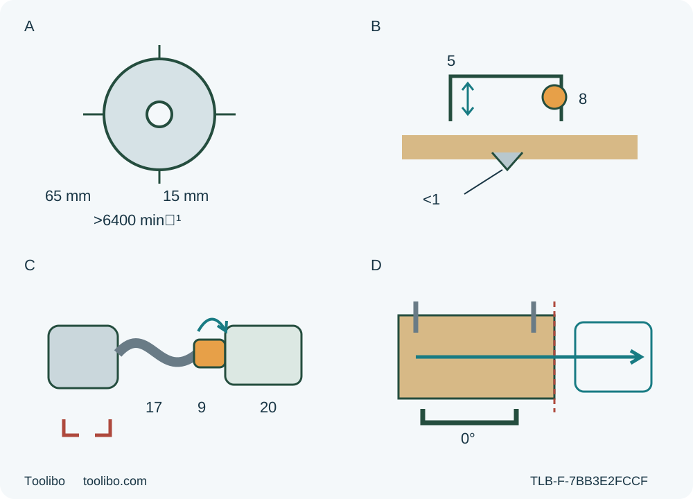
A · Match the original wood assembly
Verify actual C82 identity, material suitability, condition and the complete documented blade envelope. Diameter alone does not qualify mounting hardware.
B · Verify the actual depth
With the plug removed, set slider 5 and lock screw 8; prove less than a full tooth projects while the stock can be cut through. Unknown scale-to-actual relationship holds the task.
C · Connect and qualify extraction
Unplug before checking adapter 9 in ejector 20 and hose 17. Use the actual turn-to-click marks, then operate the qualified extractor under its own instructions before cutting.
D · Plan a genuinely clear exit
Establish support and complete cutting-arc clearance at the far outside edge before starting. An internal endpoint, binding or interrupted cut does not qualify for the normal moving lift.
The drawings are conceptual and not to scale. A qualifies the existing assembly, not replacement fitting. B requires actual less-than-full-tooth projection despite nominal scale wording; it is not a calibrated depth diagram. C is an unplugged connection check; use the actual marked turn-to-click direction. D is a planning diagram, not a live lifting pose: the whole cutting arc, support, grip and return path must qualify before use. The body preserves the model-specific normal lift/return/brief running sequence separately from binding or interruption, which requires release and motionless hold until stopped.
The Swiss PKS 16 Multi is a compact plunge-head saw, not a miniature version of every conventional circular saw. Its lock-off releases both the switch and the plunge movement, and its documented normal finishing sequence differs from the stop-and-hold response to a binding blade. This guide prepares one controlled edge-to-edge cut in known loose wood, using the existing original qualified wood blade and an auxiliary straightedge. The accepted result includes the cut, the clear exit and the returned guard—not simply a line that looks straight.
Match the Swiss body and the original wood assembly
Match the physical PKS 16 Multi, Swiss order number 06033B3000 and the complete supplied instructions to manual 1 609 92A 8R1 dated June 14, 2023. Its technical table identifies type 3 603 CB3 0..; the declaration names 3 603 CB3 000. A declaration establishes documentary identity, not a fresh safety inspection of your equipment. This is not a UK plug-conversion guide or an Australian supply specification.
Use only the already correctly installed original Precision 2 609 256 C82 assembly, qualified for the actual wood and cutting direction. That identity appears in both the current Swiss product information and the manual’s wood-blade overview. The manual specifies a 65 mm blade, 15 mm bore, maximum 1.2 mm blade-body thickness and 0.8–2.0 mm tooth thickness/offset. The blade must meet EN 847-1 and have a permitted speed strictly higher than the saw’s 6400 rpm no-load speed. A matching diameter alone does not establish a correct blade, washer, flange or bolt.
Inspect the accessible installed assembly and tool with the plug removed. Dull or damaged teeth, incorrect or damaged mounting hardware, looseness, unusual binding, misalignment or unexplained deterioration requires qualified correction before use. No blade replacement, torque sequence, flange reversal or powered fault test is taught here. The manual’s separate diamond-disc and cut-off-wheel sections do not authorize a wood-blade test or transfer their procedures to this task. Metal, plastic, tile, hidden-wall and internal-opening work are excluded.
The product’s 2.600 kg weight and the manual’s 1.9 kg figure are not reconciled here. Neither is a reason to infer that one-hand operation is acceptable. Both insulated gripping areas are required regardless of the compact size.
Establish supply, isolation and a sound return mechanism
Use a dry, clear working area and an undamaged supply arrangement that matches the actual nameplate and complete instructions. The manual allows a tool marked 230 V to operate on 220 V; it does not establish the voltage of an unidentified saw. Do not modify a plug, guess an extension-cord rating or borrow a region-specific electrical paragraph. An uncertain or damaged supply system is a hold for qualified correction.
Before inspection, depth adjustment, guide work or cleaning, switch off, wait for complete blade standstill and unplug. Keep the plug under your control. Check the switch and lock-off function with power isolated, confirm the switch is off before reconnecting, and remove any adjusting key. An unreliable switch requires repair, not repeated energized trials.
Before each use, verify that the guard moves freely, encloses the blade instantly and does not touch the blade or other parts at all documented angles and depths of cut. Check the return spring and the complete head-return action under the matched instructions, keeping hands away from teeth. This body has a sprung plunge mechanism: do not invent a separate pendulum-guard lever or force an unpowered blade into stock to test it. A sluggish, bent, damaged or obstructed return remains a service hold. Never tie the guard open.
Raising this tool allows it to spring back to its starting position and relock the plunge function. That mechanism must already be sound before a cut. Its existence does not mean that a trapped moving blade can be lifted out safely; the normal-completion and abnormal-interruption rules below have different conditions.
Connect and operate the appropriate extraction system
This workflow requires an existing qualified external extractor suitable for the actual wood dust. With the saw unplugged, push adapter 9 into chip ejector 20 and rotate it in the direction shown on the actual connection until it clicks into place. Attach hose 17 to the adapter and connect the other end to the qualified extractor. Verify the connection rather than substituting an apparently similar adapter or improvising a reducer.
Arrange the hose and power cord clear of the blade, clamps, stock edges and walking route. They must follow the complete cut and controlled exit without catching, pulling the saw sideways or obstructing either grip. Operate and check the extractor under its own instructions before cutting. The manual describes a compatible Bosch remote-start arrangement, but this article does not qualify an unidentified automatic-start socket or teach its commissioning. A connected but inactive hose is not working extraction.
Provide ventilation and use appropriate respiratory protection; the manual recommends a P2 filter-class breathing mask. It requires a special extractor for dry dust that is especially harmful to health or carcinogenic, and explicitly requires extraction for beech and oak. This sample is limited to known untreated wood with a suitable original blade, not contaminated or unidentified material. Wear safety goggles and hearing protection. Keep bystanders outside the work area and prevent dust accumulation. No numerical vacuum or airflow requirement from another Bosch model is transferred here.
Set depth by actual projection, not a guessed scale correction
Select sound, nail-free loose stock thin enough for the tool and the actual blade setup. The documented maximum depth is 16 mm, but a nominal capacity is not proof that a particular thickness leaves adequate cutting clearance. Reject a layout that requires exceeding the actual depth range or cannot accommodate the blade below the work.
With the plug removed, loosen depth screw 8, move slider 5 to the required setting and retighten screw 8. Check that the setting cannot shift. The manual describes the scale setting as material thickness plus tooth height, yet explicitly requires less than one full tooth to project beneath the work. Treat the scale as a nominal setup reference and verify actual geometry safely with power isolated. Do not convert that wording into permission for a complete exposed tooth or invent a fixed subtraction from the scale. If the actual strict projection limit and through-cut clearance cannot both be established under the complete instructions, hold the task.
Keep supports and clamps outside the entire blade sweep, including the slow entry and controlled return. The boundary marks on the base show the cutting edges at maximum depth; they are not universal start/stop distances for every depth. Do not use them to guess that the trailing teeth have already cleared a far edge.
Plan the entire path, including the exit
Use a manageable workpiece on stable supports. Secure the retained portion with clamps; support both resulting portions near the cut and edges as needed to avoid sagging, without bridging or pinching the kerf. The waste must be free to separate, not held by a hand or squeezed against the retained piece. Never hold stock across a leg. Keep the base firmly supported and guided on the retained work, not on a piece that will fall away.
Fasten a straight, sound auxiliary board securely to the workpiece as the manual permits. Guide the base against it; do not treat this as a joined proprietary rail system. Fold CutControl window 7 forward and identify the square-cut mark 19. Establish the actual blade/mark/contact-side relationship on suitable scrap before transferring a finished dimension. The figure shows the kerf relative to the wanted boundary; neither the mark nor the guide has a universal offset. Place the whole kerf on the waste side of the required dimension.
The intended cut runs from an accessible outside edge completely through to a clear far edge. Before connecting power, establish an entry position with the base securely supported and the guarded blade clear, then a continuous guided path and a normal exit where the whole cutting arc can clear the material while the saw remains controlled. There must be room to raise the tool without striking the guide, supports, clamps, cord or hose. If safe support, reach, complete clearance or return cannot be established for the actual geometry, choose a different qualified setup or obtain help; do not substitute an internal stop line.
Check reach and clearances beside or safely above the path while unplugged and guarded, without tooth contact or forcing the guard against uncut stock. Keep both gripping areas accessible and the body to one side of the blade line. A successful stationary check does not authorize a live fault test, but an unsuccessful check is enough to stop preparation.
Make the sample and distinguish the two stopping cases
Confirm the qualified extractor is operating, the switch is off and the adjustment key is removed before connecting the saw. Hold insulated handle 11 and auxiliary gripping surface 10 firmly with stable footing. Keep hands out of the cutting area, underside of the work and chip ejector. At the planned supported edge-entry position, press lock-off 1, then press and hold switch 2. The switch cannot be latched on. Allow the blade to reach operating speed before slowly lowering the head into the planned cut; prevent the base from shifting sideways.
Advance evenly and gently along the guide. Do not force the feed, twist the tool or pull it backwards. Watch the line and support behavior from a safe position rather than reaching below the work. Long spiral chips from some with-grain cuts can obstruct the ejector; loss of effective extraction or abnormal behavior requires stopping, not clearing a live outlet.
Normal completed cut: use the previously qualified clear exit, with the complete cutting arc clear of the material and neither piece trapping the blade. Following this model’s normal finishing instructions, lift the tool off the work under control, allowing the sprung head to return and the plunge function to relock, and keep it running for a few more seconds. Then release switch 2. Maintain control until actual complete standstill and guard coverage before setting it down. Unplug before measuring, touching cut pieces or changing the layout. This is not a brake-time promise and is not a general finish sequence for another saw.
Binding, interruption or an unclear exit: release the switch and hold the saw motionless in the material until the blade stops completely. Do not use the normal lifting sequence to remove a moving blade from an unfinished, pinched or obstructed kerf, and never pull it backwards while moving. Isolate after standstill, investigate and obtain appropriate correction. This guide does not teach an in-kerf restart or extraction of a trapped tool. A planned finish that becomes uncertain is an interruption, not permission to continue lifting.
Accept the result before repeating it
With the tool unplugged, measure the retained dimension at the relevant stations, inspect straightness and squareness, and check both faces and the exit for unacceptable tearing, burning or incomplete separation. Confirm that the guide and depth lock stayed secure, the base remained controlled, extraction worked and the head returned fully without interference. A correct dimension cannot compensate for a compromised guard or an uncontrolled exit.
Ordinary guide-setting corrections require isolation and another suitable scrap sample. Unexplained vibration, repeated binding, loose hardware or uncertain return remains a qualified-service hold. Keep the tool and ventilation openings clean; brush accessible guard-area dust away with power disconnected, without opening the blade assembly or adding a chemical-cleaning recipe. Supply-cord replacement belongs to Bosch or its authorized service. Store the isolated tool and accessories carefully. The outcome is one documented, repeatable loose-wood setup within this exact body’s controls—not permission to use every material or plunge operation advertised for it.
Models referenced