
Four isolated checks before the G-model sample
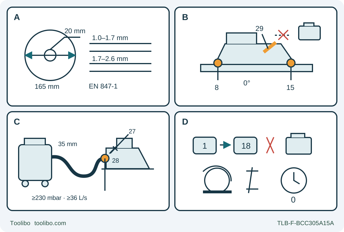
A identifies the 165 mm blade, 20 mm bore and EN 847-1 requirement. B separates depth lever 29 from the two G bevel locks 8 and 15, with a detached battery. C highlights the saw-end extraction connection after the hose, adapter 28 and screw 27. D distinguishes lock-off 1 then held trigger 18 from removing the battery.
A · Qualify the original assembly
Confirm the complete 165/20 mm blade envelope, EN 847-1 marking, permitted speed and correct original installation; do not fit a replacement from this diagram.
B · Isolate and secure the G controls
Remove the battery, clamp depth lever 29 with less than a full tooth exposed, and secure both bevel bolts 8 and 15 at zero.
C · Verify extraction at the tool
Require at least 230 mbar and 36 L/s at the saw connection; fit adapter 28 with screw 27 only when external extraction is connected, never a dust bag.
D · Separate starting from isolation
Lock-off 1 precedes held trigger 18. Release to stop, wait for standstill and guard coverage, and remove the battery before any setup change.
This is a controls-only planning diagram, not a blade-fitting or live cutting sequence. A qualifies the existing assembly; diameter and bore alone are insufficient. B requires the battery removed, less than one full tooth below the work and both zero-bevel locks secured. C places the required 230 mbar and 36 L/s at the tool connection; 35 mm is the recommended hose size, and adapter 28 needs screw 27 as well as its click. D shows the control sequence only: release the trigger, wait for actual standstill and guard coverage, and remove the battery before adjustments. Neither lock-off nor braking is isolation.
A GKS 18V-57 G can make an ordinary guided cut without turning the first sample into a guide-rail experiment. The useful starting point is the actual G body, its correctly fitted wood blade and a battery system whose compatibility and charging instructions are already established. This workflow ends with a measured square sample and an assessment of the setup, not merely a separated piece of wood.
The document used here is Bosch 1 609 92A D2M, dated 27 March 2026. The current UK product page identifies order 06016A2101 and machine 3601FA2100, and links this manual. Match those identifiers and the G suffix on the actual tool. The manual also covers the non-G GKS 18V-57; its bevel hardware and cut-mark numbering are not interchangeable with the G model. Read the complete supplied instructions before working, and stop if the actual machine or its instructions do not match this scope.
Establish the assembly and power prerequisites
This is an existing-owner procedure for known, untreated wood, with the original correctly fitted, undamaged blade, flanges and retaining hardware. It is not a blade-replacement recipe. The G specification is a 165 mm blade with a 20 mm bore, a blade body between 1.0 and 1.7 mm thick, and a tooth cutting width between 1.7 and 2.6 mm. The blade must meet the manual’s EN 847-1 requirement and have a permitted speed at least as high as the maximum speed marked on the tool. The documented no-load speed is 3,400 rpm. Diameter alone cannot establish suitability.
Check the existing assembly’s identity and condition without taking it apart. A blade with uncertain installation, damage, unsuitable teeth or missing identification is a reason to stop and obtain the complete matched instructions or qualified assistance. Do not adapt a different bore, guess a fastening direction, substitute an abrasive wheel or use a high-speed-steel blade. This sample does not authorize metal, plastic, internal plunge cuts or a table-mounted conversion.
Use only the actual genuine approved battery and charger combination already commissioned under both of their complete instructions. The D2M family lists are not enough to establish an unidentified charger’s mains supply, charging sequence or indicator meanings. This article makes no carton-content promise and does not teach a new charging system. The owner must already have completed the prescribed first full charge and know the exact pair’s normal ready condition. An uncertain, damaged or modified pack, charger or compatibility record stops the exercise.
The tool’s recommended charging ambient range is 0–35 °C; its permitted operation and storage range is −20–50 °C, with limited performance below 0 °C. The actual battery and charger instructions still apply. Do not use these tool-level ranges to override a stricter limit on the actual pair. Keep a detached pack away from conductive loose objects, heat and moisture, and never open or repair it for this task.
Remove the battery and inspect the operating system
Start with the trigger released and the battery removed. The battery mounting has two retention levels: use its release and withdraw the pack without force. Keep it detached throughout inspection, depth and angle changes, guide positioning, hose work and the stationary travel rehearsal. The lock-off button, a stopped motor and an electronic protection shutdown are not substitutes for this physical separation.
Check that the lower guard moves freely and returns immediately, without contacting the blade or another part, at all angles and depths of cut. A sluggish guard, damaged spring, bent component, loose base or switch that does not operate correctly requires correction before use. Do not clamp the guard open. Keep hands away from the teeth and do not reach beneath the work to check a live blade.
Identify both insulated grips, the lock-off switch 1 and trigger 18. The G has depth lever 29 with scale 30, and two bevel wing bolts, 8 and 15. Find both bolts rather than copying the non-G instruction that mentions only one. Check that the blade path, guard movement and ventilation openings are clear; remove loose chips with a brush while the pack is out. Cleaning is not permission to dismantle the guard or service the motor.
Qualify extraction at the saw, not at the vacuum motor
Prepare eye and hearing protection, suitable respiratory protection and good ventilation. D2M requires dust-reducing measures and suitable extraction wherever possible; this workflow requires external extraction suitable for the selected wood. Beech and oak specifically require extraction. Unknown coatings or treatments are outside the exercise, not a reason to guess a filter requirement.
The current manual specifies at least 230 mbar vacuum and 36 L/s flow at the tool’s extraction connection. The recommended nominal hose diameter is 35 mm, and the recommended filter efficiency is dust class M. A vacuum’s headline free-air flow or motor power does not demonstrate performance through the actual hose, fittings and filter at the saw. Establish the installed system’s suitability from the relevant equipment instructions and verification; do not proceed merely because a hose can be pushed onto the port.
With the battery removed, the matching adapter 28 is pushed onto chip ejector 16 until it clicks, then secured with screw 27. This is not a click-only fitting. Fit that adapter only with external extraction connected, and never attach a dust bag to it. Check that the connection is secure and that hose routing cannot tug the saw, obstruct the lower guard or catch the work clamps. If suction falls during work, stop and eliminate the cause rather than compensating by feeding faster.
Set a square cut with less than one full tooth exposed
Choose a manageable scrap of known wood whose thickness is comfortably within the actual installed configuration’s capacity. The G table gives maximum depths of 57 mm at zero and 42 mm at 45 degrees, but capacity is not a target depth setting. A 12 Ah battery reduces cutting capacity, and a bevel cut is shallower than the depth scale suggests. This workflow stays square and checks the real blade projection rather than relying on a headline maximum.
With the battery still out, loosen lever 29, move the saw relative to its base to set depth, and retighten the lever. Less than the height of one full tooth should project below the work. Inspect that relationship with the stationary assembly safely positioned; do not touch the teeth. Confirm that the clamped setting cannot shift. A lever that will not hold is a fault to resolve, not an invitation to improvise the manual’s separate lever-readjustment procedure.
Loosen both G bevel bolts 8 and 15, set the scale to zero, and secure both. Check the square relationship with an appropriate square without putting fingers against the teeth. Do not proceed with only the front fastener tightened. Recheck depth and free guard movement after the angle is secured. The ordinary sample tests the zero setting; it does not establish accuracy at other angles.
Support the retained piece and establish a real cutting reference
Mark the retained dimension and waste side before arranging the supports. Support and clamp the wood on a stable platform, never against a leg or in a free hand. For a large panel, support both sides near the cutting line and near the outer edges, without putting any support in the blade’s path. The retained portion must continue to carry the broad base as the cut finishes. The offcut must not sag into the kerf or become a lever that pinches the blade. If its final behavior is uncertain, change the setup before starting.
Use a sound straight board clamped as an auxiliary guide, as in the manual’s ordinary-guide Figure E. The saw’s base runs against that straight edge; it is not engaged in a proprietary rail. Measure the actual base-edge-to-kerf relationship with the installed blade and confirm it on scrap. Keep the guide on the supported base side and secure it against movement. Do not count the guide itself as sufficient workpiece support.
The G feature list identifies 0° mark 10 and 45° mark 11. The separate cut-mark diagram on page 22 is explicitly for the non-G model and reverses those numbers; its left-edge drawing is not a universal instruction for this G body. Use the actual G zero reference as an initial sighting aid, then establish where the real kerf falls on the sample. Keep the intended dimension on the retained side and correct the guide offset only with the battery removed.
Rehearse the entire travel while isolated. Both grips must remain available, the base must stay flat and supported, and the hose, clamp handles and guide must clear the motor housing and guard from entry to exit. Stand to the side of the blade line with stable footing. Avoid a layout that requires reaching over the cut, changing hand position near the blade or chasing a falling offcut.
Make the sample and judge the whole process
When all checks pass, clear the area, start the extractor as instructed, and insert the qualified ready battery until securely engaged. Keep the trigger released while fitting it. Place the base at the start with the blade clear of the wood. Hold both grips, operate lock-off 1, then press and hold trigger 18. The trigger does not lock on. Let the blade reach operating speed before entering the edge, and guide the saw evenly with gentle forward pressure.
Keep the base against the guide without twisting the blade sideways. Excess pressure that slows the blade is not productive feed. If the saw binds, release the trigger and hold it motionless until the blade has stopped; do not pull a rotating blade backward out of the kerf. Remove the battery before investigating the support, alignment or obstruction. A protection shutdown is also a stop to investigate, not proof that the setup is acceptable or permission to press the trigger repeatedly.
Finish the normal cut with the retained base still supported. Release the trigger and wait for actual standstill and guard coverage before setting the saw down. The manual describes a run-out brake that shortens coasting; it does not make a rotating blade safe to touch or guarantee instantaneous stopping. Remove the battery before measuring or changing the setup.
Check the retained dimension at more than one point, the edge’s straightness and squareness, and signs of burning, tearing or changing kerf width. Also judge whether the guide moved, the wood shifted, the offcut closed the kerf or extraction weakened. A correctly sized piece does not excuse an unstable process. Correct the cause while isolated and repeat on scrap before moving to the intended workpiece. After use, brush chips from the guard area, keep vents clean, and store the saw and protected detached pack under their instructions. Rail, bevel-rail and plunge procedures remain outside this completed square-cut workflow.
Models referenced