
Three actions, a separate gear selector
Numbered clutch, drill symbol and hammer symbol each align with a fixed triangle; a separate 1/2 selector sits below.
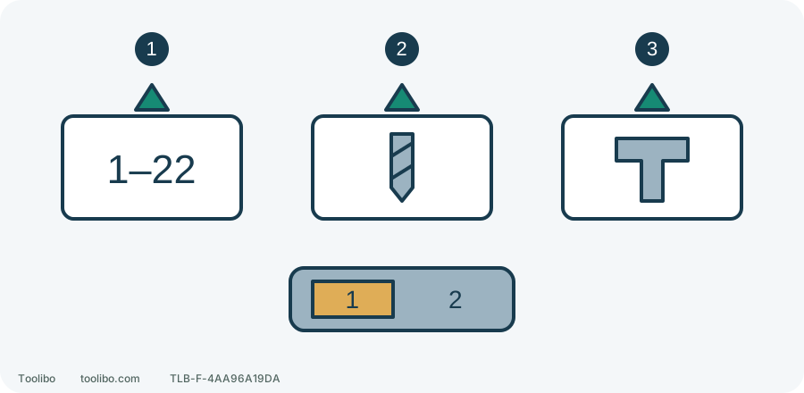
1. Screwdriving
Start low on matching scrap and judge depth and damage.
2. Rotary drilling
Use for suitable wood, metal and plastic, with their own bit requirements.
3. Hammer drilling
Only suitable masonry within the model, material and accessory limits.
Symbols are schematic, not a reproduction of the ring. The 1–22 label describes the available range: select one valid position, never an in-between point.
Identify the material before turning the ring
This concerns the North American DV18DEX and shared DEX manual C99268561G. The DS18DEX lacks this hammer action. Specified hammer applications include soft bricks and concrete blocks, not every reinforced concrete, stone, tile or unknown wall.
Identify material and exit space, exclude hidden services and obstructions, and establish diameter, depth and purpose. Structural fixings, anchors and unknown wall interiors need their own design and methods, not exploratory drilling. Prepare a suitable tool, accessory and dust-control arrangement before selecting modes.
Isolate, then align the symbol with the triangle
Smoke, leakage or rapidly worsening abnormal battery heat means keep clear, not routine removal. With stable equipment safe to approach, release, wait for standstill and remove the battery before fitting accessories and changing settings.
Find the clutch/mode ring behind the chuck and fixed triangle on the body. Align a number or valid position dot for screws, the drill symbol for rotation and the hammer symbol only for appropriate masonry. A visible symbol is insufficient unless it aligns with the fixed mark.
There are 22 clutch settings: 1 weaker, higher numbers stronger. They are neither calibrated torque values nor hole diameters. Do not leave the ring between positions, particularly on the line between 22 and the drill symbol. Do not add hammer action merely because rotary drilling is slow in a material meant for rotation; it can damage the tip.
Read gear choices with their diameter conditions
The top shift knob uses 1 for low and 2 for high; change only stopped. No-load ranges are 0–550 and 0–2000 rpm respectively. The trigger varies speed within the range; full pressure is not the required starting position.
Swipe or scroll horizontally to see all columns.
| Task | Manual gear guidance | Essential boundary |
|---|---|---|
| Brick, hammer symbol | Gear 1 to 13 mm, gear 2 to 10 mm | Rated brick capacity uses 30 mm depth, not automatic approval of every brick/job |
| Wood, drill symbol | Table metric entries: gear 1 to 52 mm, gear 2 to 24 mm; accessory limits still apply | Maximum wood rating uses 38 mm thick softwood, not all hardwood |
| Metal, drill symbol | Operating table specifies gear 2 with metalworking bit | Actual speed must suit bit/material; rated 13 mm is in 1.6 mm thick mild steel |
| Machine screws, numbered clutch | Gear 1 | The same page’s explicit low-speed warning overrides a generic gear-2 table entry |
These figures help reject unsuitable work, not encourage maximum holes. Accessory, grip, restraint and material can impose smaller limits. Use gear 1 for high-force work as required; sustained slowing or stalling means investigate, not simply increase output.
Establish screwdriving first on scrap
Clamp nonstructural scrap matching the material, use the intended screw specification and prepare its required pilot. Isolated, fit the matching driver, select gear 1, a low numbered clutch setting and correct driving direction. Finger off trigger, reinstall and secure a compatible pack. Seat the driver along the screw axis and start slowly.
If the clutch releases before seating, stop and remove the battery. Check pilot and fit before increasing one small step. After every adjustment recheck assembly and reinstall/secure the battery with finger off the trigger before trying again. Correct depth with sound recess and material permits retaining the same setup. Excess depth, splitting, cam-out or a stall means release, isolate safely and correct the cause, not increase the setting.
Do not use drill or hammer symbols to bypass the clutch in this exercise. A specified-torque or structural connection needs its design requirements and suitable installation tools, not acceptance based on one trial screw.
Prepare a small hole in suitable brick
Use identified soft-brick scrap that can be restrained, with diameter and depth within tool, accessory and workpiece limits. Choose a suitable masonry bit, inspect tip and shank and fit it securely using normal chuck instructions. Arrange eye, hearing and dust protection. Do not bring your face close to watch dust; ensure the sample cannot rotate, fracture and fall, or move with its clamps.
With battery removed, align the hammer symbol, select gear 1 or 2 according to the table and accessory, and set correct drilling direction. Check grip and exit space; finger off trigger, reinstall and secure the pack. Place the tip at the mark, hold securely, start slowly and feed axially. More pressure does not automatically drill faster.
An unexpected hard object, marked slowing, moving work, abnormal noise or twisting means release and maintain control. Stop completely and isolate safely before inspection; no repeated pulses through the obstruction. Wood and metal instead use the drill symbol and their own chip, backing and accessory requirements, not the brick procedure.
Inspect the result, not merely the extinguished light
Stop and remove the battery before handling accessories or releasing clamps, and let a hot bit become safe. Check hole location, depth, wall and surrounding material, plus chuck, accessory and controls. RFC or thermal protection does not guarantee hole quality, and an extinguished indication is not permission to proceed.
Repeated stops, loose accessories, inadequate grip or unknown cause end this setup and call for inspection. Only an identified, corrected cause with sound equipment and resecured work permits a return through normal preparation.
Models referenced