
Check the working envelope, then the controls
A drill and bit sit inside a clearance outline, with a separate battery footprint and independent range/clutch controls.
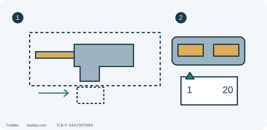
1. Entry and withdrawal
Rehearse without the battery; include its size without energising.
2. Separate settings
LOW/HIGH selects range; align a valid clutch setting with the triangle.
Conceptual dimensions only: measure the real accessory, battery and hands. The numbered ring range is not a literal scale or calibrated torque.
Check space with the real configuration
This is the US/Canadian DS18DDX, not a DS18DEX control or capacity guide. It is a drill/driver without hammer action. A small body does not make an unknown wall or an inaccessible corner suitable work.
A smoking, leaking or rapidly heating battery calls for moving clear, not routine removal. The following preparation assumes stable equipment safe to handle. Release the trigger, wait for standstill and remove the battery. Fit the actual intended bit as described below, then rehearse entry, alignment and withdrawal without power.
Measure accessory projection and available axial space. Allow room for the grip, fingers, reaction forces and the exit route. Include the chosen battery’s full envelope using its actual dimensions even though it remains removed; do not energise merely to check clearance. If you must drill at an angle, place a hand near the chuck or cannot withdraw along the axis, reposition the work or change the method.
Fit the bit using the front-of-chuck viewpoint
- Keep the battery removed. Looking from the chuck nose toward the tool, turn the sleeve counterclockwise by hand to open the jaws.
- Centre the compatible shank, avoiding cutting flutes or shoulders not intended for gripping.
- From that same front viewpoint, turn the sleeve clockwise and tighten firmly. Do not hold it while operating the motor as a substitute for hand-tightening.
- Still isolated, check for obvious crooked seating, movement or pull-out. Reseat a poor fit; repeated loosening, damaged jaws or abnormal sleeve movement mean stop, not paper shims, hammering or extra leverage.
These are normal fitting steps. A seized chuck is not an invitation to try powered release in the cramped location or to treat fitting instructions as repair advice.
LOW and HIGH have different task ranges
The top shift knob selects LOW or HIGH. Change only with the motor completely stopped. No-load ranges are 0–440 rpm in LOW and 0–1700 rpm in HIGH, not instructions to pull the trigger fully. Accessory limits, material and diameter still govern working speed.
Swipe or scroll horizontally to see all columns.
| Task | This model’s selection basis | Additional condition |
|---|---|---|
| Wood holes | Operating table lists LOW to 36 mm and HIGH to 18 mm | Maximum rated wood capacity is specified in 38 mm thick softwood, not all hardwood or cutters |
| Metal holes | Operating table lists HIGH with a metalworking bit | Control the trigger for material/bit requirements; rated 13 mm holes refer to 1.6 mm thick mild steel |
| Machine screws | Use LOW | Despite a generic HIGH entry in the table, the same page explicitly requires LOW for machine screws to avoid damage or bit loosening |
| Wood-screw trial | Start LOW with a low numbered clutch setting | Prepare the pilot required by screw and wood; extra torque does not replace it |
These are model-specific conditions, not universal rules or assurance that every numerically smaller job is suitable for handheld work. Use LOW for high-force work as required by this manual. Sustained slowing or stalling calls for investigation, not a gear change that hides poor workholding or an unsuitable accessory.
Align the setting with the triangle
For screws, align a number or valid position dot on the clutch ring with the body’s triangle. There are 20 clutch settings; 1 is weaker and higher numbers stronger. This is not a calibrated torque wrench, and the numbers are not screw sizes.
For drilling, align the drill symbol with the triangle. Do not leave the ring between valid positions, especially on the dividing line between 20 and the drill symbol. There is no hammer symbol to solve slow cutting on this model.
Establish the setting with one sample screw
Use nonstructural scrap of matching material and thickness and the intended screw specification. Clamp it and prepare the required pilot. With power isolated, fit the matching driver bit, choose LOW and a low numbered clutch setting, and select the correct driving direction using the tool markings.
Keep your finger off the trigger while reinstalling and securing a compatible battery. Seat the driver along the screw axis, then pull gently to drive slowly. Release promptly as the target depth approaches.
- Clutch releases before the head reaches its position: stop, remove the battery and check pilot and fit before increasing the clutch one small step. Recheck assembly, reinstall and secure the pack with finger off the trigger, then trial again.
- Head reaches the intended depth with sound material and recess: retain the setting for the same conditions. Changed wood or screws need another trial.
- Head goes too deep, wood splits, driver cams out or motor stalls: release immediately. Once stopped and safely isolated, investigate rather than increase the setting. Correct pilot, fit or depth control and replace damage before preparing again.
Finally check chuck retention and the screw/material result. Inadequate grip space, repeated accessory loosening, abnormal controls or unexplained shutdowns mean stop and arrange inspection. Compactness is not a reason to force the job.
Models referenced