
Align the mode, secure the grip, feed axially
Mode choices align with a fixed arrow; a grip engages barrel grooves; light axial feed contrasts with sideways force.
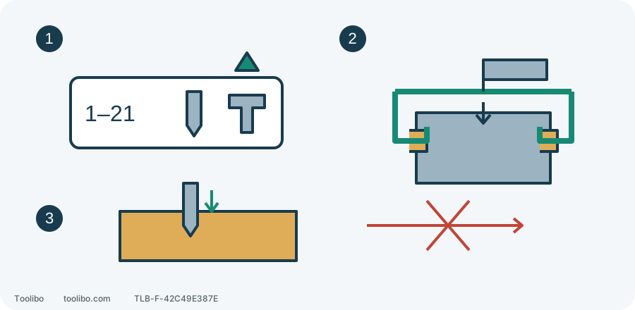
1. One selected mark
Align the number, drill or hammer mark with the arrow, never between modes.
2. Grip engagement
With battery removed, seat the arm protrusions in the grooves and secure the grip clockwise.
3. Light axial pressure
Do not enlarge the hole sideways or force an unexplained obstruction.
Conceptual geometry, not exact assembly dimensions or literal ring layout. XPH16 grip is optional; fit the correct accessory when the task needs its control.
What each selection does
This concerns the US XPH16, not the two-mode XFD16. A smoking, leaking or rapidly and abnormally heating battery means move clear, not routine removal. With normal equipment safe to handle, release, wait for standstill and remove the battery before identifying the ring behind the chuck and fixed body arrow.
Swipe or scroll horizontally to see all columns.
| Mark aligned with the arrow | Action | Decision |
|---|---|---|
| Number within 1–21 | Rotation with clutch-limited output | Screw trial adjusted for the actual joint |
| Drill symbol | Rotation only | Suitable wood, metal and corresponding rotary-cutting accessories |
| Hammer symbol | Rotation with percussion | Masonry confirmed suitable for hammer drilling with the correct bit |
Turn the ring to align the selected mark accurately. Do not leave it between modes or change while rotating. Clutch numbers are not calibrated torque, and 21 is not hammer mode. Poor rotary drilling calls for checking material, accessory and feed, not automatically selecting percussion.
The top speed selector displays 1 for the low-speed/high-torque range and 2 for higher speed/lower torque. These are mechanical ranges, not clutch settings. Shift only after complete standstill and engage fully, never between 1 and 2.
Prepare the accessory and grip before the trigger
Keep the battery removed. Choose a sound bit matching material, diameter and model capacity. For normal fitting, looking from the chuck nose toward the tool, open the sleeve counterclockwise by hand, centre and fully insert the bit, then tighten clockwise securely. Grip the suitable shank, not a crooked bit forced straight. Check obvious misalignment, loosening and damage; do not grip the sleeve and use motor power to tighten.
The XPH16 side grip is an optional accessory; the manual describes improved stability in heavier loads. If the task needs extra control and you lack a correct matching grip, obtain it or change the method, rather than improvising pipework. Seat the arm’s protrusions in the matching barrel grooves, choose the appropriate left/right position and turn the grip clockwise to secure. Check full seating and retention while isolated; do not use an assembly that will not secure.
The adjustable depth rod is also optional. Loosen its clamp screw, set the planned position and retighten. It helps repeat depth, not prove absence of wiring behind the hole or replace an anchor maker’s required depth.
Confirm the material before percussion
The following is only for known, visible, securely held nonstructural masonry scrap suitable for hammer drilling. Unknown walls, tile faces, reinforced concrete, structural anchors and concealed services are excluded. Match the bit to chuck and task. The manual specifies a tungsten-carbide tip, but carbide alone does not approve every shank interface or diameter.
Arrange eye, hearing and dust protection and material-appropriate extraction under local requirements. Do not blow dust toward your face or sweep it into the air. Check exit, depth and clamps, stable two-hand control and restraint against workpiece rotation. If any item is unconfirmed, do not connect power.
Follow the confirmed-hole sequence
- Isolated, check bit seating, side grip and any depth rod. Align hammer mark with the fixed arrow. Select a range according to exact tool, bit and material requirements; the selector must engage fully and never shift while rotating.
- Check workholding and protection. Keep your finger off the trigger while inserting and securing a compatible battery, then select correct drilling direction from the markings.
- Hold firmly, place the tip at the target and start slowly in contact. Maintain the axis with light pressure, not sideways hole enlargement.
- If cutting slows markedly or debris clogs the hole, do not add pressure. Release, stop and isolate safely. Distinguish ordinary debris from bit damage or an unexpected hard obstruction before appropriate treatment; do not repeatedly pull the trigger with an unknown cause.
- On completion release and wait for standstill, then remove the battery safely to inspect hole and accessory. Let a hot bit cool before handling.
The manual warns of sudden twisting at breakthrough, clogging and contact with reinforcing rods. This trial therefore does not prescribe more force or powered reverse extraction of a trapped bit. Stop when reaction is abnormal or control insecure; change tool/method or seek professional help as needed.
Re-establish the clutch when returning to screws
Stop and remove the battery, allow safe cooling and fit the matching driver. Align a low numbered clutch position with the arrow and choose a suitable low-speed range. Clamp matching nonstructural scrap and prepare the screw’s required pilot.
Check settings, reinstall and lock the battery with your finger away, select correct driving direction and seat the driver fully along the axis before a slow trial. Early clutch release before seating means stop, remove battery and inspect pilot/fit before a small increase. Correct depth without damage means retain. Excess depth, splitting, cam-out or stalling means stop and correct the cause, not increase again.
After every adjustment recheck the assembly and reinstall/secure the battery before another trial. Do not leave hammer mode selected for screws or bypass repeated clutch release with drilling mode.
Models referenced