
Reposition the grip, then check the whole tool
Top-view grip rotation is followed by a secured position and a frame-clearance check including the collector.
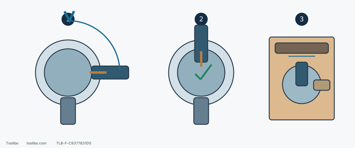
1. Loosen and move horizontally
Support the body and loosen the grip enough to move its base; keep fingers clear of the abrasive.
2. Retighten and check security
The base must hold its chosen position under normal handling; extra leverage is not a repair for worn threads.
3. Check the complete outline
The dark rail represents the nearby frame. Check grip, housing and collector clearance with the pad flat.
Symbolic geometry, not an assembly drawing or specified handle angle. Adjust only with the plug removed.
Identify the fixing
The front grip is the handhold, its base surrounds the body, and the grip screws onto the base’s threaded section. Adjusting it does not require opening the motor housing or loosening pad screws. Switch off, wait for movement to stop, unplug and support the tool.
Do not compensate for a cracked grip, damaged base or worn thread by tightening harder. Replace the correct part or obtain service.
Adjust the position
- Support the housing and loosen the front grip enough to move its base horizontally. Complete removal is unnecessary for a simple adjustment.
- Choose a position that allows one hand on the rear handle and the other naturally on the front grip. Keep fingers away from the abrasive and moving parts.
- Retighten the front grip. Hold the body and check for looseness or base rotation under normal handling.
- With power still disconnected, rehearse the entire planned pass, including the narrowest point, far end and return.
Do not invent a tightening torque, add an extension for leverage or glue a worn thread. If normal assembly will not hold its position, stop using it.
Refit a removed grip assembly
Open the grip base and fit it around the body at the Makita-logo area. Close the base, then screw the front grip firmly onto its screw section. Start the thread straight rather than forcing it at an angle. To remove the assembly, loosen and remove the front grip first, then take off the base. Distinguish repositioning from complete dismantling, and verify missing, bent or unidentified parts before assembly.
Check housing and collector clearance
Near a frame, moving the grip may reveal that the housing or dust bag is the next obstruction. Place the pad flat on the intended face and inspect the whole outline: front grip, rear handhold, housing, bag and cord.
If access requires tipping the pad, an insecure one-handed hold or removing necessary dust collection, change the work orientation, fixture or method. An adjustable grip is not permission to enter every recess.
Before switching on
The grip must be secure, the base closed and the threaded joint sound. Both hands should fit naturally while the pad remains flat, with clamps and leads clear in both directions. Then use BO5041’s normal operating sequence for a trial.
Stop if the grip moves or develops play in use; wait for a complete stop and unplug before checking. Do not retighten while running. These are mechanical grip instructions; use the actual nameplate and applicable regional instructions for voltage and electrical supply.
Repeat the clearance check when turning the tool toward a different edge. A dust bag that cleared the first pass may now face a clamp. A secure front grip does not guarantee room in the new direction. With power disconnected, reorient the workpiece and arrange the clamps before discovering an obstruction during sanding.
Models referenced