
Makita DF333DZ UAE: set the clutch without borrowing DF033D instructions decision map
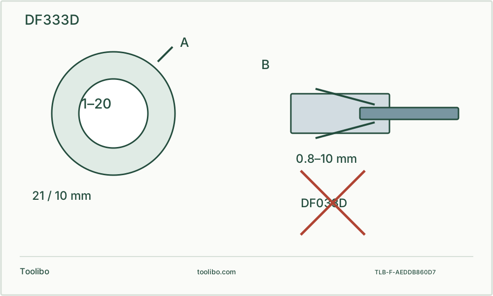
A ring marked 1–20 sits beside a chuck section whose jaws grip the plain shank; DF033D is crossed out to exclude its different holder instructions.
Identity
Use the DF333D chuck section, not DF033D sleeve instructions.
Trial
Start low on matching scrap and inspect the seated screw.
Limit
A fitting shank does not override the 21 mm wood capacity.
Original adjusting-ring schematic separates numbered positions 1–20 from the drill symbol; a second cross-section shows chuck jaws gripping a plain shank, with DF033D hex sleeve explicitly outside scope.
Separate the sales suffix from the tool family
The UAE product listing calls this tool DF333DZ and describes a tool-only CXT model, without a battery or charger. Its English manual covers DF333D and DF033D together. The extra zero in DF033D matters: that model uses a different bit-retention arrangement. The chuck instructions marked DF333D are the relevant ones here. Do not order a sleeve or follow a hex-holder removal sequence simply because both names occur in the same PDF.
The manufacturer’s regional listing is evidence of this UAE model identity, not a promise of dealer stock across the Middle East. Check the nameplate and the supplied document before purchase or maintenance. The selected manual file is identified as DF333D_ENEU_885672A226; its specification warning says regional differences are possible. A seller’s battery bundle must be checked independently.
Plan around the small chuck and actual work
The stated chuck range is 0.8–10 mm, with drilling capacities of 21 mm in wood and 10 mm in steel. Those are different dimensions. A large cutter with a reduced shank does not become suitable merely because it enters the chuck. This is particularly important for a 35 mm hinge cup: choose a properly rated drill and fixture instead of treating the small shank as approval.
For a cabinet pilot hole, identify the screw, board and required depth before choosing the bit. Mark both the intended entry and the area that must remain intact on the far side. Remove the panel where practical so you can restrain it, inspect both faces and eliminate hidden-service uncertainty. Do not turn this removable-part example into a wall-drilling procedure.
Fit the bit with the battery removed
Check the trigger returns freely, then keep the tool switched off and remove the battery before fitting the accessory. Turn the chuck sleeve to open the jaws, seat the intended shank and tighten the sleeve by hand. Check that the bit is straight and retained; never run the motor while holding the chuck to tighten it. Keep the jaws off the flutes and any unsuitable transition in the shank.
The battery must latch fully when reinstalled. The manual uses a visible red indicator to warn of incomplete seating. Do not force a mismatched pack or use an adapter to connect an unrelated platform. Keep your finger off the trigger while fitting the compatible battery, and confirm there is room for both the pack and the supporting hand in the cabinet opening.
Use numbered settings for a trial screw
The adjusting ring has numbered positions 1–20 plus the drilling position. The numbered positions allow clutch action; the drilling position does not. The manual’s wording about 21 levels should not be read as 21 calibrated torque settings. Select screwdriving control and try the actual screw in a matching offcut, starting low and adjusting only as needed.
Choose gear 1 or 2 only while stopped and fully seat the selector. The listed ranges are 0–450 and 0–1700 rpm. Use a slow controlled start and keep the bit aligned with the recess. Release when the clutch acts instead of repeatedly rattling it against a screw already seated. A chewed recess, split board or crushed surface means the pilot, alignment or setting needs correction, not more trigger pressure.
Drill the pilot as a separate operation
Switch off, isolate and exchange the bit before changing to rotary drilling. Secure the panel and any backing as one stable arrangement. Keep fingers, clamps and the bench outside the bit’s full path. The body has no hammer mode, and there is no reason to imitate percussion by pushing and releasing the tool against the panel.
Use suitable speed for the bit and material and feed along the bit axis. Ease feed as a through-hole approaches the exit. For a blind hole, stop at the verified depth rather than waiting for a visual sign on the opposite face. Inspect the first hole and trial screw before repeating the setting across a door. Neither a clutch number nor a battery gauge confirms the hole is correctly located.
Interpret stopping without opening the tool
The manual distinguishes overload, an overheated battery and low remaining charge. Stop the work that caused overload; if the tool does not restart normally, allow appropriate cooling and check charge according to the instructions. Do not defeat protection, continuously pulse a jam or swap fresh packs to sustain an unsuitable load. For continuous use that exhausts a pack, the manual calls for a 15 minute tool rest before continuing with a fresh one.
Clean and inspect externally with power removed. Persistent abnormal noise, looseness, damaged casing or repeated stops on a suitable task require professional service. Record DF333D, the actual battery identifier, the bit and what happened. Avoid handling a smoking, leaking or dangerously hot pack as a routine test.
Models referenced