
Offset is not the same as a right angle
Three cabinet access sketches compare a blocked straight axis, an offset axis and a right-angle path; 35 mm is crossed out beside the 32 mm wood limit.
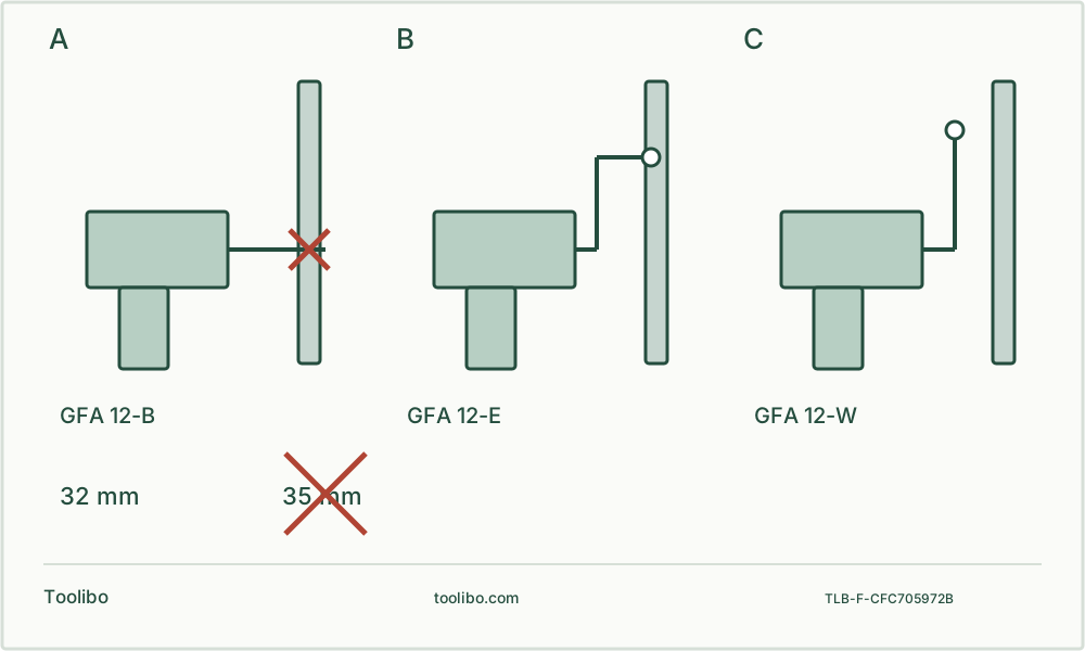
Axis
Choose straight, offset or angled access for the actual screw.
Retention
Remove the battery and check both accessory and head locks.
Capacity
A 35 mm cutter is outside the listed 32 mm wood limit.
Plan the actual bit axis and housing clearance; changing the access direction does not increase the permitted hole diameter.
Check the box number before planning a confined job
This guide covers the UK GSR 12V-35 FC package 06019H3003, with tool-family number 3 601 JH3 0.. in manual 1 609 92A 9UL dated 09.10.2024. The selected package lists the GFA 12-B chuck, GFA 12-X locking bit holder, GFA 12-E offset head, GFA 12-W angle head and an L-BOXX. Do not assume another suffix supplies the same heads or a battery. Record the actual tool number separately from the package number.
The useful buying question is whether access, rather than drilling power, prevents the job. For example, a screw close to a cabinet side may need the offset head; a rear-facing screw may need the angle head. A small body alone cannot solve either geometry. First measure the opening with the actual screw, bit, fitted head and battery included. Leave room for your hand and a controlled withdrawal path.
Choose the output, not just a head that fits
Swipe or scroll horizontally to see all columns.
| Part | Purpose | Important boundary |
|---|---|---|
| GFA 12-B | Holds suitable round or hex drill shanks in a 0.8–10 mm chuck | Chuck opening is not the permitted hole diameter |
| GFA 12-X | Retains a suitable 6.35 mm hex accessory | Correct retention matters when withdrawing from a recess |
| GFA 12-E | Moves the screw axis towards an edge | Check that housing and fingers clear the neighbouring surface |
| GFA 12-W | Changes the direction of access | The installed combination must still permit secure control |
The current manual allows another adapter to be fitted onto the angle adapter after the angle adapter is locked to the tool. This is not permission to stack arbitrary brands or use a loosely seated extension. Lay out only the specified parts needed for the task. More joints add space and inspection points; they do not increase the drill’s capacity.
Isolate, assemble and check retention
Remove the battery before changing a head or bit. Remove the accessory from the tool holder before installing an adapter. Seat the adapter and turn its locking ring until it engages audibly. Check that the assembly is retained before bringing it to the work. A click with visible incomplete seating is not an acceptable setup.
For the offset or angle head, pull the adapter forward, select one of its 16 indexed positions and release it to lock. Do this without power, not while the bit is engaged in a screw. With the GFA 12-B, tighten the chuck sleeve by hand around the intended shank. Do not grip the sleeve while pressing the trigger. Inspect both the accessory grip and the head-to-tool connection; either can be the source of movement.
Run a removable-wood rehearsal
Clamp a known, uncoated scrap that represents the cabinet joint, with no hidden metal or services. Arrange eye protection and wood-dust controls, keep loose clothing clear and confirm that the bit can enter straight. Test a suitable pilot and matching screw using the clutch at a low setting, then adjust only enough to seat the screw correctly. Clutch numbers are repeatable positions, not calibrated torque values.
Select the gear only while stopped and push the selector fully into position. The listed no-load ranges are 0–460 and 0–1750 rpm; these are not instructions to run every accessory at maximum speed. Use its permitted speed and suitable material settings. When the screw is seated, release rather than using the locked spindle as an excuse to add excessive hand force.
Reject jobs outside this configuration
The documented wood and steel drilling limits are 32 mm and 10 mm. A 35 mm concealed-hinge cutter exceeds that wood figure even if its shank fits GFA 12-B. Choose a suitable drill and fixture instead. The base tool has no hammer-mode selector. The current manual also names GFA 12-H, but that rotary-hammer system needs its own matched instructions and is outside this four-head guide; a GFA 12-W is not its substitute.
These checks do not authorize hidden-wall work, hazardous dust collection or operation with the tool braced against your body. If the head’s geometry forces a bent wrist or prevents a firm grip, change the work position or equipment rather than accepting poor control because the bit reaches.
Separate a setup fault from a protection stop
If the bit or head moves, release, wait for a complete stop and remove the battery before checking seating and damage. Do not catch a rotating head. If drilling binds, stop immediately; repeated trigger pulses are not a clearing method. The manual describes a three-light chasing pattern during temperature-related protection. Let the tool recover normally and reduce the cause of overload, without opening the housing or bypassing protection.
After the task, isolate the tool, clean exposed surfaces and ventilation openings appropriately, inspect the locking interfaces and store the heads where grit cannot collect in them. Persistent play, abnormal noise, repeated stops under appropriate load or damaged retention parts need qualified assessment. Keep the full nameplate number with the service report.
Models referenced