
Kreg 320 pocket holes: match thickness, collar and screw before the first joint decision map
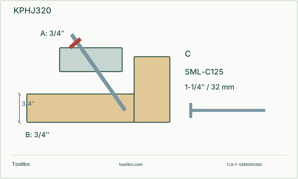
An angled drill path and two joining boards link the 3/4-inch collar and material-stop settings to an SML-C125 screw of 1-1/4 inches or 32 mm.
Measure
Use actual thickness of both joined members.
Set
Match the material stop and Easy-Set collar.
Verify
Clamp and test the complete joint before repetition.
Original angled-pocket section shows three independent references: board thickness, guide stop at the board edge and collar-limited travel; a screw path ends within the receiving board rather than through its visible face.
Measure the stock, including the mating piece
This guide uses the Kreg KPHJ320 and its Easy-Set stepped drill, stop collar and material-thickness stops. It covers a new, removable non-structural wood joint that can be clamped on a bench. It does not approve repairs to load-bearing furniture, a stair, a building connection or an unknown damaged component.
Measure the actual stock rather than using a shop label such as three-quarter-inch board. Also measure the piece that receives the screw. A correct hole in one board can still send an unsuitable screw through the second. Note grain direction, material type, edge condition and the faces that must remain visible. Start with duplicate offcuts that reproduce the intended joint, not an unrelated thick scrap that hides excessive penetration.
Link the three setup decisions
The manufacturer gives a material range from 1/2 to 1 1/2 inches, with common marked settings at 1/2, 3/4 and 1 1/2 inches. Use the matching gauge and the manual’s thickness-range chart. Intermediate material is not a reason to position the collar by eye between unrelated marks. Keep the exact jig revision and bit together.
Swipe or scroll horizontally to see all columns.
| Check | What it controls | If it is wrong |
|---|---|---|
| Material-thickness stop | Jig position against the board edge | The pocket can exit at an unsuitable location |
| Easy-Set collar | Drill travel through the guide | The pilot or screw seat can be incorrectly formed |
| Correct pocket-hole screw | Engagement in the receiving member | The joint may split, protrude or fail to seat |
The chart’s sample screw lengths are conditional on thickness range and joint material. They are not permission to use a general countersunk screw or to copy a long screw from a different joint. If the receiving board differs from the chart’s intended setup, resolve the fastening specification before proceeding.
For a limited bench example, use two sound pine offcuts each actually measuring 3/4 inch, in a non-load-bearing face joint. The matched chart uses the 3/4 mark for both the Easy-Set collar and material stop, with a 1-1/4 inch (32 mm) pocket-hole screw. The manual lists SML-C125 coarse-thread sample screws; match that pocket-hole head and thread for this example rather than substituting a drywall screw. Clamp the joint, trial at a low clutch setting and inspect for splitting or a protruding point. Different thickness, hardwood or a different joint invalidates this example.
Adjust with the drill disconnected
Remove the battery or disconnect the supply before fitting the drill bit or adjusting the collar. Use the Easy-Set marks as the manual directs and tighten the collar with the provided wrench. Set each material stop to the corresponding position and check it is engaged. A loose collar that slips under feed defeats the setup even if it began at the correct mark.
Arrange the guide spacing for the actual board width. Inspect the stepped bit for damage and the guides for contamination. Do not sharpen away or substitute an important step and then assume the old setting still applies. Keep the drill’s chuck on the intended shank and verify retention without running the motor against your hand.
Clamp the jig and keep the chip path open
Put the material stop against the intended board edge, hold the guide square to its reference and clamp it securely. Restrain the workpiece itself as well; clamping a jig to a loose small board does not stop the whole assembly turning. Position the clamp so it does not block the chip-ejection opening or the drill’s path.
Use eye, hearing and wood-dust protection appropriate to the job. Follow the matched drill and jig instructions for speed and controlled travel. Do not press harder because chips are trapped. Stop and isolate before clearing a blocked passage or touching the bit. A hand holding the jig is not a substitute for a clamp, and the jig’s repair-screw mounting method is outside this bench-work guide.
Trial the joint before repeating the holes
Drill the sample pocket, stop, isolate and inspect its entrance, screw seat and exit. Then clamp the two sample pieces in their intended relationship before driving the specified pocket-hole screw. Use a controlled screwdriving setup rather than hammer mode. Keep the joint faces aligned so the screw cannot pull an initially misplaced assembly into a deceptive position.
Inspect for a protruding point, a crushed pocket seat, a split receiving member or a gap between faces. Do not use extra torque to close a gap caused by poor preparation. A screw that spins without holding has not become secure because the head looks flush. Recheck thickness, jig position, screw specification and material condition independently.
Record an accepted setup and stop at damage
Once the sample passes, record the actual stock thickness, bit identity, collar mark, material-stop setting and screw choice. Recheck after moving the jig, changing boards or noticing a different hole shape. Mixed offcut thicknesses can invalidate a previously successful setting even within one project.
Stop if the drill binds, the guide shifts, the collar moves or the bit is damaged. Wait for a complete stop and isolate before inspection. Persistent misalignment or an uncertain joint requirement needs a revised plan rather than progressively deeper holes. The aim is a repeatable, verified joint, not simply a row of pockets that look alike.