
SKIL JS313101 or JS314901: compare foot and speed controls · Diagram
Two level feet compare a hex-key adjustment with a raised locking lever.
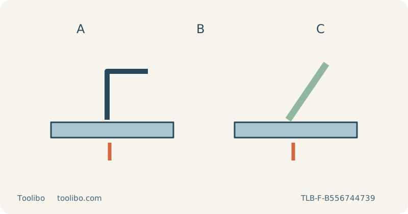
A
Identify the screw system
B
Identify the lever system
C
Verify a square sample
Two level feet compare a hex-key adjustment with a raised locking lever.
Start with the exact US corded pair
The SKIL JS313101 and JS314901 compared here are US corded jigsaws identified for 120 V, 60 Hz supply. Their rated inputs are 5 A and 6 A respectively. Those figures identify the models; they do not by themselves prove which will leave a cleaner edge in a household panel. Compare the manuals and nameplates before using a familiar-looking control or moving an accessory between them.
This comparison is limited to loose, known, uncoated wood. The JS314901 product page and manual disagree on a metal-capacity figure, so this guide does not turn that inconsistency into a recommendation. It also makes no hands-on ranking of speed, vibration or longevity. The practical comparison is how the foot adjustment, speed controls and visibility fit a task you can support safely.
Compare foot adjustment with both plugs removed
The JS313101 foot is secured by a hex screw. Follow its documented loosening and shifting sequence, place the locating features in the chosen position and tighten the screw as instructed. The JS314901 uses a bevel lever to unlock and secure its foot. Do not assume the lever means that locating features can be ignored; the foot still needs to seat correctly before it is locked.
For the first trial, set both to zero bevel. With power disconnected, check that the base remains secure and its contact surface is clean. A tool-free control changes the adjustment workflow, not the need to verify the result. If a foot rocks because of damage, shifts after locking or cannot be fixed by its normal mechanism, stop and arrange service rather than comparing how hard you can hold it down.
Match blade compatibility and stop habits
Both checked manuals permit the specified common T-shank and U-shank blade types. Select a sound blade suitable for the wood, thickness and route rather than choosing only by shank. With the plugs removed, insert the blades fully through the correct clamp procedure, keep their backs in the roller guides and check retention. A compatible shank does not guarantee that a broad blade will turn a tight curve or a short one will clear thick stock.
Learn the trigger and lock-on release sequence for each tool before plugging in. Leave lock-on unused for a short first sample. The JS313101 provides its variable-trigger control; the JS314901 manual also describes a separate variable-speed dial. Identify the actual controls instead of treating the two tools as interchangeable merely because both have two-finger triggers in their product descriptions.
Compare visibility without overlooking workholding
The JS314901’s front light can help show the marked line, but it does not illuminate every hazard underneath the board. Both tools still require a clear route, stable support and appropriate dust control. Compare whether the line remains visible with the actual blade, orbital setting and permitted blower arrangement, rather than assuming that a brighter work area necessarily produces a more accurate edge.
Clamp matching samples on a stable bench and support the waste independently so it cannot fall or pinch the kerf. Leave clearance for the complete blade stroke below, and keep clamps out of the full base route. Run the cords behind the saws, where neither blade nor departing waste can catch them. Wear eye and hearing protection and suitable respiratory protection, with compatible extraction where available and good ventilation.
Use repeatable samples to decide what matters
With the base supported and the blade clear, start each saw and establish an appropriate speed before feeding. Keep the sole flat and avoid excessive forward or sideways force. Stop on binding, loss of contact, unexpected movement or a caught cable. Wait for a complete blade stop before withdrawing or setting down, then unplug before adjustments, blade inspection or changing workholding.
Inspect both faces and the cut-face angle, not just the illuminated top line. If the sample is unacceptable, change one clear factor before repeating it. Consider the frequency of permitted base-angle changes, your preferred speed-control routine and the available workspace rather than assuming that the higher input rating settles the purchase. A successful sample establishes a useful arrangement for that material, not a universal ranking. Repeat the check when thickness, blade profile or required fit changes, and stop using either tool if electrical or retention faults appear.
Models referenced