
Align the intended start with the displayed reference
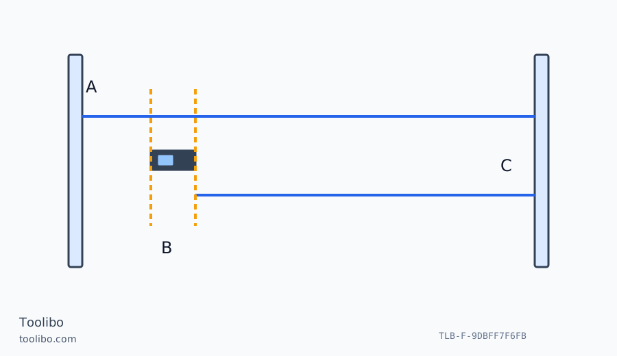
One instrument is shown between wall planes, with separate rear-start and front-start paths to the same target.
A
Identify the physical starting contact.
B
Check which edge the selected reference represents.
C
Compare the same target and path before judging the discrepancy.
A consistent difference can come from setup geometry; do not apply a guessed housing-length correction to old records.
Draw what the displayed distance represents
A laser leaves the front window, but the displayed measurement may begin at the rear housing edge, front edge, tripod axis or an extended endpiece. The available choices depend on the exact model. The documented GB GLM 40 has a fixed rear reference, while some other meters allow a choice. Similar appearance does not establish an identical reference menu or automatic behaviour.
Draw the starting wall, the target wall and the instrument between them. Mark the physical contact and the reference shown on the display. If those points do not agree, the result can differ systematically from the distance you intended. Routinely adding the housing length may introduce a second mistake rather than correct the first. Establish the geometry before discussing an offset.
Use a reproducible span for the comparison
Choose a moderate indoor span between stable opaque surfaces that can also be checked directly. Position the meter correctly according to its instructions, take a reading, then lift and replace it. Record the reference each time. Avoid glass, soft furnishings and the edge of a target for this initial check because they introduce other possible causes of variation.
If the discrepancy appears only after moving from a wall contact to a tabletop edge, examine the reference first. If it varies unpredictably, inspect movement, target selection and whether the laser or receiver window is obstructed. A consistent difference is a useful clue, but it does not by itself prove that the instrument requires calibration. A stable wrong setup can also produce stable wrong results.
When using a tape as the comparison, identify its actual start and finish. Do not assume that two methods described as wall-to-wall are measuring identical surfaces. A tape hooked against skirting and a meter positioned above it may be measuring different spans even when both readings are internally consistent.
Correct the setup rather than the whole notebook
Once a reference problem is understood, remeasure the important distances with the correct setup. Do not apply one correction to an old survey unless every affected setup and endpoint is actually known. Different entries may have used different references, target faces or support arrangements. An unlabelled list rarely provides enough evidence to repair all of them retrospectively.
For a selectable-reference instrument, change the setting only as its own manual describes and place the corresponding edge or axis at the start. Do not assume that switching the unit off restores your preferred setting. Check the display whenever the arrangement changes. On a fixed-reference model, change the placement or measuring method rather than searching for a menu that the instrument does not have.
If the discrepancy remains despite correct positioning, follow the exact model’s accuracy-check and service guidance. Do not open the meter, move optical components or defeat protection. Keep the beam away from eyes, people and optical instruments. This investigation does not certify measurements for structural work or safe installation clearances.
Separate an apparently constant error from a placement change
Suppose a tape and laser disagree by roughly the instrument’s length. That is a good reason to inspect the reference, but it is not permission to subtract the housing length from every reading. The tape may start at skirting while the meter starts at the wall above it. The laser target may be a cupboard face rather than the opposite wall. Several endpoint mistakes can resemble a reference error.
Draw both measurement paths on the same sketch. Mark the tape’s endpoints, the selected laser reference and the illuminated target. Align the paths before comparing numbers. Keep their heights consistent and check that neither method follows a diagonal when the intended quantity is the perpendicular separation. Comparing different geometry cannot establish which instrument is more accurate.
Use a deliberate change-and-return check if the wall setup seems repeatable but the tabletop arrangement does not. Keep the target and height unchanged, return to the wall setup, and see whether the earlier result returns. If it does, inspect which instrument edge met the tabletop mark. This sequence helps distinguish a placement change from random variation without inventing a correction value.
If neither setup is stable, stop looking for a fixed offset and record the conditions for the prescribed check or service enquiry. Keep old and corrected notes distinguishable so another person does not continue using a superseded photograph or copy. Remeasuring a clearly identified span is safer than constructing a convincing explanation for an untraceable number.
Models referenced