
Temporary target and wall offset
Original schematic: The laser ends at the target front. Measure the target-to-wall separation. Derive the intended span only from known geometry. Not to scale.
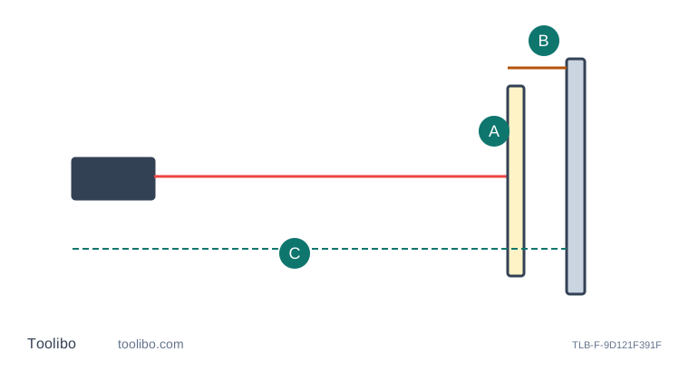
A
The laser ends at the target front
B
Measure the target-to-wall separation
C
Derive the intended span only from known geometry
Conceptual geometry only, not to scale. The diagram does not establish installation clearances or reproduce a manufacturer control layout.
Name the surface that the laser actually reaches
A temporary matte target can provide a clearer measurement surface when the intended boundary is difficult to use. However, the meter measures to the target surface, not automatically to the wall behind it. If a board sits in front of that wall, the displayed span ends at the front of the board. Calling that result the wall distance hides an offset that may matter to the project.
First identify the desired endpoint and the temporary target’s actual face. Draw a side view showing the two planes. Decide whether you can place the target directly at the desired plane without creating a hazard. Secure it before measuring and keep people out of the beam path. Never aim the laser at a person holding a target, and do not use optical magnification to locate the spot.
Work out the sign from the drawing, not from habit
Consider a hypothetical setup in which the target’s front face is 0.020 m in front of the desired rear wall, along the same measurement line. If the meter reads 3.480 m to that face, the intended wall distance would be 3.500 m after adding the known 0.020 m separation. This is an arithmetic example, not a tested correction or a universal target-board thickness.
The addition is valid only because the target lies closer to the meter than the desired endpoint, and because the separation is known along the relevant line. A different target arrangement can require a different calculation. Do not memorise “always add the board thickness.” A spacer, a gap behind the board or an angled placement can make the actual offset different from the material’s nominal thickness.
Check placement and geometry before accepting the correction
A board that rocks, bends or tilts does not provide a single dependable plane. A reading taken near one edge may end at a different distance from the wall than a reading near the other edge. Support the target in a normal, stable way and identify where the spot falls. If the face cannot be positioned and described reliably, use a different direct measuring method instead of creating a more elaborate correction.
Also preserve the starting reference. Correcting the target end does not fix a front-versus-rear reference error at the meter. The two issues are independent. Confirm which physical part of the instrument defines the start, then check the target offset. If both ends have uncertain offsets, combining them into one guessed number will not create a trustworthy distance, even when repeated readings agree.
Preserve the raw result and decide whether the method is suitable
Record the displayed distance, the measured offset, its direction and the derived distance separately. That lets another person see what was observed and what was calculated. If the board is moved, the offset must be checked again; a correction from one room or one position should not silently follow the target elsewhere. Keep the unit identical across the calculation.
For a planning estimate, a clearly defined temporary target may be useful. For a fitted part with tight tolerances, use the supplier or installer’s required final measurement method. Do not assume the arithmetic removes uncertainty in the board’s placement, the wall surface or the instrument. If the actual wall is inaccessible, label the result as derived and explain the target arrangement rather than presenting it as a direct wall reading.
The target should remain an external accessory used within the meter’s instructions. Do not modify the optical window, cover the receiver with improvised filters or open the housing to improve a difficult return. A stable display is only evidence that the instrument returned a value under that setup; it does not independently validate your chosen endpoint. If the setup remains ambiguous, retake the dimension with a method that directly reaches the required boundary. This is often simpler and more defensible than adding corrections whose physical meaning is no longer clear.
Models referenced