
Skirting runs and stock allocation
Original schematic: Mark the doorway interruption. Retain each uninterrupted wall run. Allocate actual cuts to stock lengths. Not to scale.
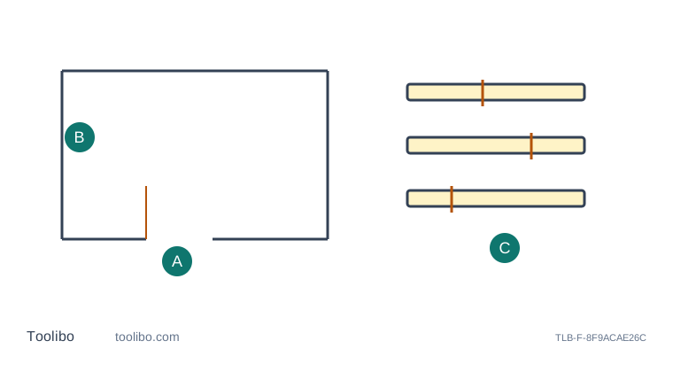
A
Mark the doorway interruption
B
Retain each uninterrupted wall run
C
Allocate actual cuts to stock lengths
Conceptual geometry only, not to scale. The diagram does not establish installation clearances or reproduce a manufacturer control layout.
Identify the faces that will actually receive trim
A room perimeter is a useful starting number, but it is not a cutting plan. Door openings interrupt skirting, projecting features create additional returns, and cupboards may conceal areas that will not receive new trim. Draw the finished wall faces at the height where the trim will sit. Mark every opening and every change in direction before adding lengths.
Decide whether existing skirting will remain during the survey. Measuring between its exposed faces gives a different geometry from measuring the wall behind it. If it will be removed later, identify the resulting uncertainty rather than guessing its hidden thickness. Use a tape for short returns and corner details that do not permit a clear laser measurement. Do not remove fixed fittings or disturb connected equipment just to obtain an otherwise inaccessible dimension.
Separate the nominal total from individual pieces
Consider an illustrative rectangular room 4.00 m by 3.00 m. Its perimeter is 14.00 m. If one 0.90 m doorway interrupts the trim and there are no other changes, the nominal wall length requiring trim is 13.10 m. This simple subtraction is not an order quantity: it excludes cutting losses, joints, returns and any difference between the measured wall boundary and the chosen trim profile.
Now write the actual uninterrupted runs rather than only the 13.10 m total. A long wall divided by a doorway creates two separate pieces, whose lengths depend on the doorway’s location. Those pieces may fit efficiently into stock lengths, or they may leave unusable offcuts. Two rooms with the same total trim length can require different numbers of boards because their individual runs differ.
Plan stock use without assuming every offcut is reusable
Obtain the product’s actual supplied lengths and the installer’s joining method. A nominal stock length may not all be usable if an end is damaged or needs trimming. Corner joints and cut orientation can also affect whether an offcut fits another location. Do not count the same leftover length against two separate runs, or assume that an offcut with the wrong end treatment can be used without further loss.
Make a simple allocation list: one stock piece at a time, showing the intended wall segments cut from it and the remaining length. Allow for the cutting process and the actual joint requirements rather than adding a universal percentage. If a long run needs a joint, agree its position with the installer; the most economical division is not always the preferred visible finish. The measuring plan should describe the room, while the cutting plan reflects the chosen material and installation method.
Resolve corners and ordering before fabrication
Inside and outside corners deserve separate attention. A laser distance along a wall does not tell you the corner angle or the exact finished length of a mitred profile. Do not assume every corner is a right angle. The installer may need direct angle checks, templates or fitting measurements after old trim is removed. Keep those requirements separate from the preliminary length survey.
Check that every return around a chimney breast, alcove or boxed-in feature appears once in the list. A large enclosing rectangle can hide those extra faces. Conversely, a face permanently covered by a cabinet may not belong in the installation scope. Confirm the intended finish with the person doing the work before converting the list into an order.
Keep the measured run lengths, proposed cuts and purchase reserve as separate records. If the trim product changes, its supplied lengths or profile can change the cutting plan without changing the underlying wall measurements. Never use this survey to infer that a fixing point is free of concealed services. Keep the laser away from eyes, people and optical instruments, and obtain final fabrication dimensions by the installer’s required method. A well-built cut list explains where the material will go and which details still need fitting; a perimeter alone cannot do that.
Models referenced