
Frame widths and equal visible gaps
Original schematic: Define the available composition width. Count frame widths separately from gaps. Fixing points depend on the actual hardware. Not to scale.
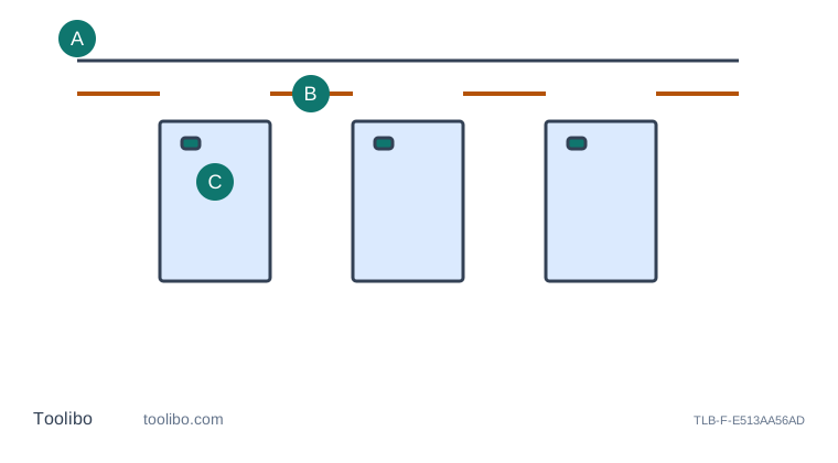
A
Define the available composition width
B
Count frame widths separately from gaps
C
Fixing points depend on the actual hardware
Conceptual geometry only, not to scale. The diagram does not establish installation clearances or reproduce a manufacturer control layout.
Define the composition before measuring positions
An evenly spaced row can mean equal gaps between frames, equal distances between frame centres or equal margins at the ends. Those are different layouts when frame widths differ. Start by choosing the visual rule you want and drawing the outside edges of the frames. Measure the actual frames, not only the print size advertised on the packaging. A wide moulding or projecting decorative edge changes the occupied width.
Identify the usable wall strip and its boundaries. A light switch, furniture edge or door swing may make the full wall width irrelevant to the composition. Measure between stable, identifiable surfaces with the laser supported, and use a tape for the small frame dimensions. Keep the measuring line at the height relevant to the layout. A reading along a skirting board can describe a different plane from the wall where the pictures will hang.
Calculate equal visible gaps using the occupied width
Suppose an illustrative usable strip is 2.40 m wide and three frames are each 0.40 m wide. Together, the frames occupy 1.20 m. That leaves 1.20 m for the spaces. If you want equal space at both ends as well as between the frames, there are four spaces, so each is 0.30 m. This is a planning example, not a suggested spacing for every wall.
If instead you want the outer frames to define a 2.40 m overall group width, only the two internal gaps receive the remaining 1.20 m. Each would be 0.60 m. Both calculations are arithmetically valid, but they answer different design questions. State which boundary is fixed before making marks. Confusing the two rules can create a row that is neatly measured yet visually unlike what you intended.
Treat mixed frame widths and hanging hardware separately
With unequal frames, equal gaps do not produce equal centre spacing. Add each frame’s actual width in sequence, placing the chosen gap between outside edges. Keep calculations in one unit and convert small distances deliberately rather than mixing metre readings with unlabelled centimetre notes. A paper template of each outside frame can make the layout easier to evaluate before any fixing work is considered.
The hanging point is not necessarily the frame centre. A single hook, two brackets or a hanging wire can require different horizontal and vertical positions. Measure the actual hardware according to its instructions. Do not assume that a wire’s resting position on a table matches its loaded position on the wall. For heavy or valuable objects, use appropriate rated hardware and competent installation advice. The laser does not assess wall strength or determine the capacity of an anchor.
Rehearse the layout and separate it from installation
Place full-size paper outlines or another non-damaging temporary layout on the wall where practical. View the composition from the normal seating or entrance position. Check that the row does not interfere with a door, switch or intended furniture position. A calculated layout can still look wrong if the useful visual centre is a sofa rather than the geometric centre of the entire wall.
If you adjust one frame, recalculate the adjacent gaps rather than silently moving the others by eye. Keep the final outside-edge positions separate from the eventual fixing marks. This preserves the design if you change a frame’s mounting hardware. Check the overall width by adding the individual frame widths and all intended spaces; this catches a missing gap or a duplicated end margin before installation.
Do not use the result as evidence that a drilling position is clear of concealed services. Fixing safety is a separate task involving the wall construction, service locations, hardware and object weight. Never point the laser toward eyes, people or optical instruments, and do not hold a beam at face height while someone studies the layout. Turn it off once the needed distances are recorded. The useful outcome is a checked composition with explicit margins and gaps, not a row of unexplained numbers or an unverified set of holes.
Models referenced