
Prove a permitted bevel on a loose wood test piece · Diagram
An inclined blade passes diagonally through a board; a vertical reference and lower horizontal arrow show its sideways reach.
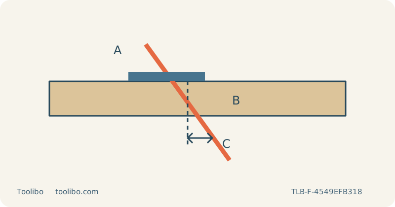
A
Lock the permitted base angle
B
Check the angled material path
C
Clear the sideways sweep below
Check permitted Bosch accessories, tilted blade clearance and both faces of the sample.
Use a test piece to answer a specific fitting question
A bevel changes the relationship between the upper line, the lower cut edge and the space swept by the blade. Before cutting a household part, make a sample in the same known, uncoated wood and thickness. Decide which face provides the dimensional reference and which side is waste. A bevel that looks correct from above may leave the lower edge on the wrong side of the intended joint.
This guide uses the Bosch GST 18V-125 B and S instructions for permitted external setup. It does not claim that a printed angle mark produces furniture-joint precision, and it does not apply to concealed work or an installed panel. If the fit demands a repeatable angle beyond what the sample establishes, choose a more suitable method instead of compensating by forcing the saw sideways.
Remove accessories that are not permitted for the bevel
Switch off and remove the battery before adjusting the base, changing a blade or moving dust attachments. On these Bosch models, the dust hood, extraction outlet and anti-splinter guard are not used for bevel cutting as specified by the manual. Remove incompatible components using the documented procedure before tilting the footplate. Do not force them around the new angle or modify an opening to obtain clearance.
Follow the model’s footplate adjustment sequence, choose the permitted angle and secure the fastening. Check that the base stays fixed before reconnecting power. An anti-splinter insert suitable for zero bevel must not be assumed safe at a tilted setting. Its removal also changes the surface-finish arrangement, so a straight-cut sample with that insert cannot establish the finish of this bevel cut.
Check the tilted blade below the board
Fit a suitable compatible T-shank wood blade fully, with its back in the guide roller, and check retention. Confirm that its usable length is sufficient for the actual angled path through the board throughout its stroke. Do not select length solely from the board’s vertical thickness. Check the accessory’s application and the tool’s permitted limits rather than treating maximum wood capacity as an angle-independent guarantee.
Clamp the retained sample on a stable bench and independently support the waste. Inspect the entire swept path below the board: a tilted blade reaches sideways as well as downward. Move supports and clamps outside that space, including near the intended exit. Keep the base’s reduced contact arrangement stable throughout the route. If support cannot remain secure, revise the setup instead of relying on hand pressure to balance the saw.
Make a short controlled cut
Wear eye and hearing protection and suitable respiratory protection, and provide ventilation appropriate to the dust. Because this documented bevel setup excludes the standard hood and extraction outlet, do not imply that the straight-cut extraction configuration is still operating. If suitable dust control cannot be maintained for the work and setting, choose another process. Keep any cable or permitted accessory clear of the route without attaching improvised collection hardware to the guard.
With the base supported and the blade clear of the wood, start the saw and establish the selected speed before feeding. Follow a short straight route, keeping the base in contact and avoiding sideways force. Stop if the footplate shifts, the blade binds or the saw becomes difficult to control. Wait for a complete blade stop before withdrawing, setting down or checking the sample, then remove the battery before any adjustment.
Check both geometry and practical fit
Compare the sample against the intended mating piece or an appropriate angle reference. Inspect the cut from both faces and at several points along its length. Separate a consistently wrong angle from a changing cut caused by deflection or uneven support. Do not move the footplate to compensate for a single poor cut before checking blade condition and feeding technique.
Once the sample meets the actual requirement, mark the reference face and record the verified setup. Transfer it cautiously to the finished blank, allowing for the kerf and the direction of the bevel. Recheck waste support and underside clearance rather than assuming the short trial proved the longer route. When returning to zero bevel, isolate power, restore the correct base position and only reinstall accessories permitted for that new setup.
Models referenced