
Separate torque numbers from the function ring
Two adjacent rings are separated by leaders; a locked-clutch icon connects rotary and hammer concepts while 13 mm points only to the chuck.
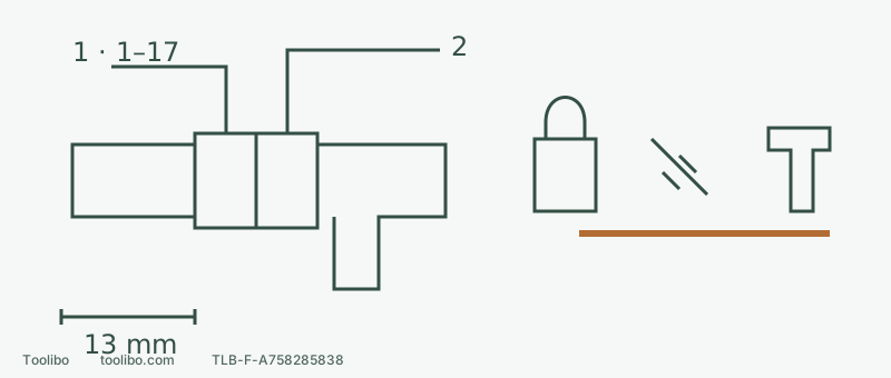
1 · Numbered clutch for driving
In screw-driving function, begin at 1 on matching scrap and increase only after inspecting the result.
2 · Drilling and hammer lock the clutch
Align the required function while stopped and isolated; a low number does not limit every binding reaction in these modes.
Conceptual control map, not exact ring artwork. No verified masonry maximum is supplied here; chuck size cannot fill that missing specification.
Locate two rings and one range selector
Behind the chuck, the forward numbered ring adjusts torque. The adjacent function ring has screw-driving, drilling and hammerdrilling marks; the top slider independently selects two mechanical ranges. Align the required function with the tool’s indicator. The highest clutch number does not select hammer action.
US HD6294B-00 no-load ranges are 0–500/0–1,800 rpm, with impact rates 0–7,500/0–27,000 per minute. They describe different movements, not hole-completion time or permitted diameter. Fully engage range 1 or 2, never changing it during rotation.
Decide whether hammer action belongs in the task
Swipe or scroll horizontally to see all columns.
| Task | Selection | Checks still needed |
|---|---|---|
| Ordinary screw trial | Driving function and low numbered clutch | Bit, screw, material, pilot hole and seating requirement |
| Wood, metal, ceramic or plastic drilling | Rotary drilling, not hammer | Material-specific accessory, capacity, support and speed |
| Suitable brick, concrete or other masonry work | Consider hammer only after assessment | Percussion-rated masonry bit, diameter/depth, workholding and dust controls |
The manual recommends carbide-tipped masonry bits but does not provide a verified maximum masonry-hole diameter table. Its 1/2-inch (13 mm) specification concerns the chuck, not permission to drill 13 mm concrete holes. For a specific hole, give SKIL or a qualified supplier the actual tool version, material, bit and depth. Do not fill the gap with another brand’s capacity.
Unresolved coatings, concealed services or structural conditions rule out a trial hole. Nor does tile appearing in a masonry-bit application paragraph permit hammer mode: the manual explicitly prohibits hammering tile to avoid damage. This is a mode and configuration check, not an unassessed wall-drilling procedure.
Why a low clutch number is not universal protection
Driving has positions 1–17; this manual says to begin at 1 and increase until the required action is obtained. Drilling and hammer functions lock the clutch for their tasks. Position 1 is therefore not a cross-mode reaction-torque limit.
Do not switch a troublesome screw to drilling to bypass the clutch. Check bit match, pilot hole, whether it is already seated and whether the material is splitting. Binding or motor stalling differs from normal clutch release.
Make the settings in a stopped, isolated sequence
First observe the battery from a safe distance. Smoke, leakage, swelling or unusual heat means do not approach or handle it; stop and contact the manufacturer. For normal equipment, release the trigger, wait for a complete stop, centre-lock the direction and remove the battery before accessories, rings or gears.
- Choose a verified suitable accessory with a clean, sound shank. Insert it axially and hand-tighten according to OPEN/CLOSE. Never hold the chuck and power it to tighten.
- Align the required function mark with the indicator. For a screw trial, also set the numbered ring to 1. For drilling or hammering, do not treat that number as a torque limiter.
- Select the range for the actual task. Low range suits the manual’s driving and appropriate higher-torque work; high range suits appropriate lighter drilling. Not every masonry task automatically uses high.
- Clamp the work and confirm grip, withdrawal and dust conditions. Install and latch the specified battery with your finger off the trigger, release the centre direction lock and choose the correct rotation before a controlled slow start.
Watch the first result
For ordinary screws, check seating appropriate to the design and intact recess and material before deciding whether to stop, disconnect and raise the number. For an approved drilling task, monitor alignment, cutting and control. Failure to cut, overheating, chuck slip or lost dust control means stop, not more pressure or repeated trigger pulses.
Every setting change repeats stopping, isolation and safe restoration. If the material differs from the plan, return to material and accessory verification instead of probing further. Correct mode is only one starting condition, not a substitute for the right accessory and site assessment.
Models referenced