
Open the hooks, seat them, then tighten
Exploded and seated sections show hooks spanning mounting ribs, with a separate aligned hammer symbol below.
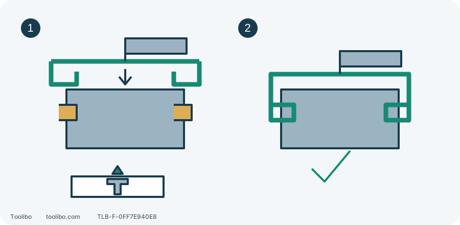
1. Loosen and position
Battery removed: turn grip counterclockwise, open hooks and place over mounting ribs.
2. Seat and secure
Check both slots, tighten clockwise and verify no movement before use.
PBLHM101 mounting principle, not exact part dimensions. Both hooks must enter the specified slots behind the torque ring before tightening.
Match the model to its controls
This guide uses PBLHM101 sections of combo manual PBLCK02K, 998000632 REV01. The other tool, PBLID02, is an impact driver: its 1/2/3/A button and quick-change hex collet do not belong to this hammer drill.
PBLHM101 has a top two-speed selector and a torque ring behind the chuck with numbers, drill and hammer marks. Its operating number groups end at 22, followed by drill and hammer positions. “24 positions” does not mean 24 numbered clutch settings. Identify these on the isolated tool, not by repeatedly pulling the trigger.
Seat the handle hooks in the mounting-rib slots
A smoking, leaking or rapidly heating abnormal battery means move clear, not ordinary removal. For stable equipment safe to handle, release, wait for standstill and remove the battery.
- Locate the mounting ribs behind the torque adjustment ring. The handle does not clamp onto the rotating chuck or an arbitrary area of plastic housing.
- Turn its grip counterclockwise to spread the hooks enough to fit over the ribs.
- Install on the suitable side, placing both hooks over the ribs and into the designated slots, not merely resting on their raised edges.
- Turn the grip clockwise to tighten. Still isolated, check movement and full engagement. Loose, deformed or damaged parts mean stop, not tape or packing.
The manual requires the auxiliary handle whenever using this tool to help resist reaction. Include both hands and handle in the access check, along with axial entry and withdrawal. If reaching requires removing it, reposition the work or change the method.
Select action, then speed range
With the battery removed, open the jaws slightly beyond the suitable shank, raise the nose slightly and insert straight. Follow chuck arrows to tighten by hand and confirm correct shank contact. Never use the motor while holding the sleeve or straighten a crooked insertion by force.
Align the chosen number, drill or hammer mark with the fixed indicator, not between positions. Mode and gear are separate: hammer is not a higher clutch number and gear 2 does not automatically enable hammering.
Swipe or scroll horizontally to see all columns.
| Task | Ring position | Starting gear |
|---|---|---|
| Screw trial | Low numbered clutch | 1; adjust gradually from scrap results |
| Suitable metal hole | Drill mark | 1; actual speed still follows material and accessory |
| Suitable wood hole | Drill mark | Appropriate gear-2 range, slow contact start |
| Known suitable masonry | Hammer mark | Manual lists masonry under gear 2; trigger still regulates actual speed |
No-load ranges are 0–500 rpm in 1 and 0–2100 rpm in 2. They are not cutting-speed prescriptions or instructions for full trigger. Shift only after complete standstill; accessory and assembly changes still require battery removal.
Prepare the first trial on known brick
Identify the brick, intended diameter and depth, and choose a carbide-tipped masonry bit suitable for it and the tool. Fitting the chuck does not approve arbitrary diameters, depths or stones. This operating guide does not provide a masonry diameter table covering every accessory. Do not use this trial for unknown walls, concealed services or structural anchoring.
Secure the sample and plan exit clearance, keeping hands, bench and clamps out of the bit path. Prepare eye, hearing and appropriate dust protection; seeing the hole clearly does not address inhalation exposure.
After checking handle, bit, hammer mark and gear, keep your finger off the trigger while inserting a compatible battery and confirm both side latches. Select correct forward drilling direction from the tool markings, hold main and auxiliary handles, put the tip at the target and begin slowly in contact. Adjust within material/accessory requirements. The manual recommends light pressure and medium speed for brick, not ever-increasing force.
If the actual surface is a fragile finish or tile, do not carry this brick exercise across unchanged. Use the specific material/accessory method rather than switching on hammer action to see whether it cracks.
Respond to the actual result
Swipe or scroll horizontally to see all columns.
| Existing observation | Response |
|---|---|
| Stable cutting with work and handle stationary | Use light pressure along the axis to planned depth, not sideways enlargement |
| Wandering tip or misplaced hole | Release, stop and isolate safely; review location and accessory, do not steer sideways inside the hole |
| Binding, marked slowing, moving work or twisting | Release immediately, retain control, stop and isolate safely before finding cause; no repeated pulses |
| Loose handle, displaced hooks or recurring bit loosening | Stop using it and correct assembly or arrange service, not finish the hole first |
To drive screws instead, stop and remove the battery, fit the matching driver and choose numbered clutch plus gear 1 on equivalent scrap. Early clutch release calls for pilot/fit checks before an isolated small increase. Excess depth or damage calls for less output and corrected technique. After every adjustment recheck and reinstall/secure the battery with finger off trigger before another trial.
Confirm retention after finishing
Stop and remove the battery before handling accessory or clamps, letting a hot bit become safe. Inspect location, depth, hole wall and sample integrity, and recheck side handle and chuck. Unexplained repeated stops or looseness end the job and require inspection. Battery reinsertion is not a repair.
Models referenced