
Straight insertion and independent controls
A raised chuck nose accepts an aligned shank; a numbered/drill ring and 1/2 gear selector are shown separately.
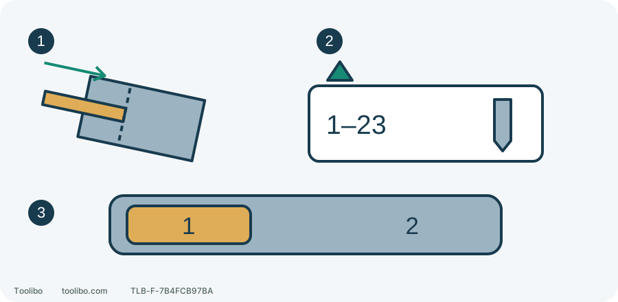
1. Straight, hand-fitted shank
Remove the battery, raise the nose slightly and follow chuck arrows by hand.
2. Ring selection
Numbers limit screwdriving; the drill mark is a different task mode.
3. Gear choice
Select 1 or 2 fully stopped, then control speed with the trigger.
Conceptual positions, not dimensions. The numeric range is 1–23 plus a drilling position; it is not a calibrated torque scale.
Identify three different controls
This guide follows PBLDD01 manual 998000372 REV02. The top switch selects the two-speed range, the ring behind the chuck adjusts torque and the selector above the trigger changes direction. Speed, driving limit and rotation direction are separate functions.
The operating instructions list numbered torque groups 1–23 plus a drilling position. “24 positions” does not mean 24 numbered calibrated torque settings. This model has no hammer action; a hammer symbol on another RYOBI does not add that function here.
Keep clear of a smoking, leaking or rapidly heating abnormal battery instead of approaching for ordinary removal. For stable equipment safe to handle, release the trigger, wait for standstill, select centre lock and remove the battery. The lock reduces unintended starting but does not replace isolation.
Raise the nose and insert straight
- Read the opening/closing arrows on the chuck. Turn the sleeve by hand until the opening is slightly larger than the shank. Do not wrench the jaws.
- Raise the nose slightly and insert the suitable bit straight, with the jaws evenly gripping the intended shank area. Do not insert at an angle and tighten it straight.
- Turn the sleeve manually in its marked locking direction and tighten securely. Never hold the sleeve with one hand and use the trigger/motor to tighten it.
- Still isolated, inspect obvious misalignment, movement or pull-out. Unreliable retention after reseating, damaged jaws or a seized sleeve means stop, not paper, tape or makeshift shims.
Use the tool’s arrows rather than an ambiguous left/right impression from different viewpoints. Normal removal follows the release arrow with power isolated; this is not a seized-chuck repair procedure.
Choose gear 1 or 2 for the load
Gear 1 suits lower speed and higher torque demand, including screwdriving and metal drilling in this manual. Gear 2 suits appropriate faster drilling/driving, including wood. Diameter, cutter type and material affect load: not every wood hole requires gear 2, and gear 1 does not make every large cutter suitable.
Stop completely before shifting. During isolated preparation, select a definite 1 or 2 position. If gears do not mesh, the manual allows turning the chuck by hand to align them before checking engagement. Never force a shift with the motor running; remove the battery and ensure safe accessory handling first, avoiding sharp edges.
Swipe or scroll horizontally to see all columns.
| Planned work | Starting choice | Stop and review when |
|---|---|---|
| Matching-screw trial | Gear 1, low numbered clutch | Splitting, recess damage, marked slowing or stall; do not keep increasing |
| Suitable identified metal hole | Gear 1 and suitable metal bit, actual speed per accessory | Rubbing, excess heat or moving sheet; review cutter and restraint |
| Ordinary wood hole | Suitable gear-2 range, drill position, slow contact start | Cutter/load unsuitable, exit binding or moving work; reconsider setup |
This task table does not supply a universal diameter limit for every accessory. A shank fitting the chuck does not establish capacity. Meet both drill and accessory limits rather than compensate with extra pressure.
Find the clutch setting on scrap
Clamp matching nonstructural scrap with the intended screw and required pilot. Isolated, fit the correct driver, choose gear 1 and a low clutch number. The manual groups 1–4 for small screws and 5–8 for soft material, with higher groups for greater demand. These are starting guidance, not guaranteed settings without trials.
Finger off trigger, reinstall a compatible pack and confirm both side latches secure. Select correct driving direction using the tool markings. Seat the bit along the screw axis and start gently. Release as the required depth approaches, not after crushing the material.
- Early clutch release before seating: stop and remove the battery, check pilot and fit, then increase a small step only if no other fault exists. Recheck, reinstall and secure the pack with finger off trigger before retrying.
- Correct depth with sound material and recess: keep that setup. Different material, screw or pilot requires another sample.
- Excess depth, splitting, cam-out or motor stall: release immediately and isolate safely before correction. Do not bypass the clutch with drill mode or pulse through resistance.
Prepare again before returning to drilling
Stop and remove the battery, fit a suitable drill bit and align the ring’s drill mark with the fixed body mark. Select the appropriate gear and direction and clamp the work. Back a wood through-hole with tightly fitted sacrificial material while preserving exit clearance; the bench must not be in the drilling path.
Finger off trigger, reinstall and secure the pack. Hold steadily, place the tip at the target and start very slowly in contact. Feed along the axis, not sideways to enlarge the hole. Be prepared for binding at breakthrough. A bind or stall means stop and isolate to find the cause. Continue similar work only with sound retention, material, hole result and controls.
Models referenced