
Isolate, unlock, secure both locks and finish
A separates the pack from an evidence card. B shows an approximate 140-degree counterclockwise lever cue and a separate 90-degree clockwise rod-removal cue. C shows neutral uncounted seating, pressed counterclockwise rod insertion and a separate clockwise lever-home cue. D is a plan-view retained clamp and independent waste support around a clear straight cutting corridor.
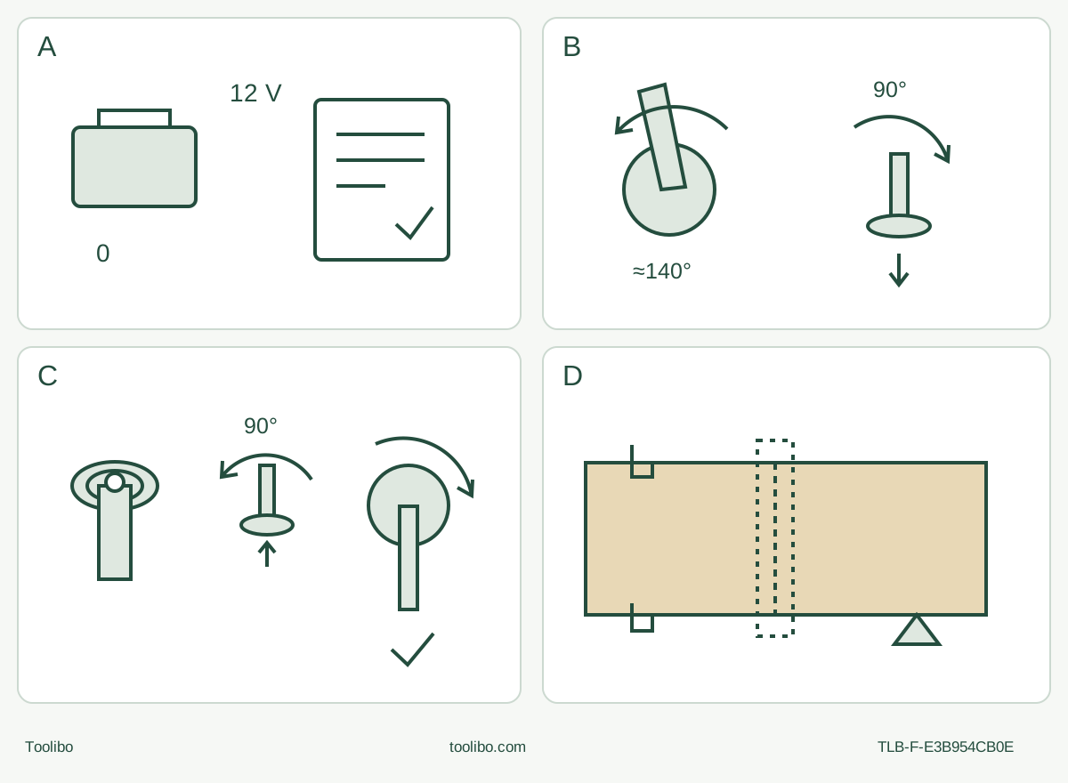
A · Isolate the matched system
OFF, complete stop, front release button and pack fully out. Exact commissioned power instructions and original blade identity must already be established.
B · Unlock and remove
Lever counterclockwise about 140° to click; rod clockwise 90° and out. Remove the cooled old accessory, with gloves and both pinch zones clear.
C · Secure rod and lever
Clean and align all actual grooves/ribs, insert and press rod through 90° counterclockwise, then lever clockwise through click to its original home. Check isolated retention.
D · Cut, stop and accept
Clamp retained stock, independently support waste and clear the full moving envelope. Use actual grip/dust/PPE, full selected speed before contact and complete stop before withdrawal; inspect both faces with pack removed.
Original schematic, not full assembly geometry or a counted rib standard. Rotation cues refer to their separate source parts; C must finish both rod securing and lever return through click to home. All change/check actions are battery-out. D adds no handle, capture port or capacity guarantee; actual soft-grip control and underside clearance still govern.
A rod lock and a lever lock must both be complete
This project applies to the actual US SKIL OS592701, matching the 08/18 owner manual and its illustrated controls and holder. The current owner card and selected product variant 41428404502613 identify OS592701, although the product address contains a kit number. Neither that address nor another package creates an additional body or proves newer battery compatibility. Match the physical nameplate and supplied instructions before proceeding.
The intended result is a short straight through-cut in a visible, dry, new, untreated and uncoated loose softwood sample, then an isolated inspection of both faces. It is not an installed-floor cut or a hidden plunge. Use the positively identified manufacturer-recommended original bi-metal plunge-cut blade represented in the manual’s page 11 material table, which explicitly includes wood. A similarly shaped aftermarket blade is not approved by this page. Confirm actual original identity, manufacturer limitations, condition and enough usable reach to cut through the chosen stock without other contact. The manual does not supply a blade SKU, numerical accessory rating or installed cutting depth for us to invent.
The tool specification is 12 V DC and 11,000–18,000 oscillations per minute. The current storefront’s RPM label is not a spindle-speed instruction. Its AutoSensing wording does not establish an operating mode in the matched manual; this project uses the documented slide switch and dial. Package counts, claimed lighting advantage and newer USB-C kits are not operating authority.
Qualify power, condition and the place of work
The selected existing system is an original BY500101 battery and QC535701 charger, already commissioned under their own complete matching instructions. The tool’s page 12 table names them, but this guide does not replace the separate manuals or teach charging. If the actual power-item identity, condition, charging history or applicable instructions are uncertain, stop. Do not modify, open or attempt to service a damaged pack. Keep detached terminals away from loose metal and keep tool, battery and charger dry; do not immerse them or let fluid enter.
The tool’s recommended working range is 14–104 °F (−10–40 °C), while storage is 32–104 °F (0–40 °C). These are not charging temperatures. Apply the actual pack and charger requirements separately, and never infer USB-C or other-current-kit pairing from a shared storefront.
Slide the switch backward to OFF, wait for complete standstill, press the release button on the front of the battery pack, and slide the pack fully out. OFF alone is not isolation. With the battery removed, inspect housing, soft grip, switch, lever, locking rod, drive shaft, accessible original fasteners and the blade. Missing, cracked, loose, damaged, modified, binding or otherwise unexplained parts require qualified correction. Reject a bent, blunt, cracked or suspect blade. Do not run the tool to prove an uncertain clamp or control.
Work alert, with stable footing, in a clean, well-lit, dry place free of explosive or flammable atmospheres. Keep children and bystanders away. Inspect both stock faces and the whole route for nails, screws, staples or other foreign material; exclude painted, treated, composite, contaminated or unidentified material. Keep hair and loose clothing away from moving parts.
Wear ANSI Z87.1 eye protection with side protection and the full-face protection required by the actual conditions, appropriate hearing protection and protective gloves during cutting as well as changes. Provide suitable dust respiratory protection, ventilation and protective clothing for the actual wood hazard, avoiding dust contact and washing exposed skin afterward. Provided extraction facilities must be correctly connected and used. Before connection, isolate the tool and extractor under their respective instructions; any selected system must be operating and checked before cutting. This manual establishes no native capture hood or port. If required exposure controls cannot be provided by documented approved equipment, hold the task rather than tape a hose nearby or assume a small sample is harmless.
Change the original blade without confusing the two rotations
Let the old accessory cool and protect against sharp edges. Keep the pack out throughout installation, inspection and adjustment. Do not point the locking rod downward during removal: an accessory could fall unexpectedly. Hold the lever securely and keep fingers out of both the lever/body pinch zone and the rod/shaft gap.
Follow pages 15–16 and Figures 6–7:
- Turn the clamping lever counterclockwise approximately 140°, until the audible click indicates the clamp has been unlocked.
- Rotate the locking rod 90° clockwise and withdraw it. Remove the old accessory; do not place a new blade over it.
- Check that the original rod and drive shaft are clean and sound. Seat the selected original blade so all its grooves align with the drive-shaft ribs. The actual rib pattern and accessory lock pattern must match; a pin count is not a compatibility standard.
- Insert the original locking rod, press it and rotate it 90° counterclockwise to secure it in the drive shaft.
- Turn the clamping lever clockwise. After the locking click, continue until the lever returns to its original home position. The click alone is not the end of the sequence.
- Check correct secure attachment while isolated. If the blade or rod remains loose, alignment is uncertain or the lever cannot reach home normally, stop for correction. No energized seating test, extra washer, adapter conversion or guessed torque is allowed.
For this straight cut, choose a forward-facing orientation that clears the full tool and work envelope. The source permits indexed positions in 30° steps, but explicitly prohibits a backward-facing plunge blade. Do not rotate the accessory after power insertion or use orientation marks as permission to reach behind the tool.
Make the fixture and cutting path work together
Mark the intended cut on both faces. Clamp the retained stock to a stable bench or fixture. Support the waste independently so separation does not cause an uncontrolled fall, kerf closure or tearing of the last fibers. Do not rigidly trap both sides of the cut. Check actual blade reach through the stock and the complete underside and exit path, including the blade’s oscillation and any permitted body movement. Keep clamps, supports, hoses and every body part out of that envelope.
The documented working hold is the actual soft-grip barrel shown in Figure 9b. Keep the free hand away from the blade, cut range and underside; it must not hold the stock. Do not invent an auxiliary handle, grip the battery or cover motor vents. If secure stock support and the actual grip cannot coexist, change the setup or stop. Both faces must remain accessible for the final isolated check.
With the switch OFF and battery still removed, preselect the setting. Dial 1 is slowest and 6 fastest, without a published per-position rate table. Page 18 calls for a medium-to-high initial range for the plunge blade; determine the suitable setting on an equally qualified scrap sample. Do not translate that phrase into a made-up exact dial number. This project makes subsequent adjustments only after OFF, full stop and battery removal, rather than teaching the manual’s separate no-load adjustment option.
Start clear and stop before withdrawal
After the isolated mounting, fixture and dust checks, keep the switch OFF, align the original battery’s raised rib with the tool groove and slide it fully into place until the latches engage correctly. A partial insertion is not acceptable. Remove loose tools from the work area, establish the actual soft-grip hold and keep the blade clear of the wood.
Push the switch forward to ON and allow the full selected speed to be reached before contact. Feed without forcing. The manual allows slow sideways movement of the back of the tool while keeping the teeth in the work surface; use that only within the previously checked full envelope, not as a license to twist a trapped blade or steer an unsupported curve. No automatic-speed marketing claim replaces controlled feed.
After complete separation, pull the switch backward to OFF and wait until the tool has completely stopped before removing it from the workpiece, as page 18 requires. Withdraw along a clear path, set the tool down safely and remove the battery before touching the offcut, blade or fixture. A jam, unusual noise, strong vibration, movement at the holder, overheating or support shift requires stopping and isolating first—not pushing harder or repeating a fault under power.
The Halo light turns on and off with the switch. Rapid flashing relates to overload/overheating protection; slow flashing indicates low battery. Neither state proves safe isolation, a correctly mounted blade or a healthy pack. A protective stop requires OFF and the actual cooling/condition instructions; this page supplies no timed restart experiment. Low charge returns to the already-qualified battery/charger instructions, not a new charging recipe. Repeated or unexplained faults require authorized service.
Accept the cut and leave the system safe
Allow hot parts to cool and avoid sharp edges. With the pack out, inspect both faces for complete breakthrough, intended line and size, and an edge free from uncontrolled tearing, scorching or evidence of fixture movement. A remaining wood bridge, wrong size or shifted support is not an accepted result. Do not snap the bridge by hand or pry with the blade. Correct a documented blade/material/fixture issue before another sample; unexplained behavior remains a service hold. No numerical tolerance or cut-capacity guarantee is invented.
Keep accessible vents and switch areas free of debris without inserting pointed objects. Avoid the plastic-damaging solvents and cleaners listed on page 22. Internal work and replacement of damaged components belong to qualified SKIL service, using the correct parts; do not service a battery pack yourself. Store the isolated tool indoors, inaccessible to children and away from corrosive agents, within the actual component storage instructions.
Evidence boundary
The controlling document is the current-linked OS592701 manual dated 08/18: full English 1–23, especially the material table 11, power table 12, controls 13–14, original holder 15–16, plunge operation 18 and care/diagnostics 22. The exact owner card and product variant establish the current link, not every kit’s compatibility or supplied revision. Other blades, sanding, scraping, grout removal, newer power systems, price, stock and warranty promises are outside this completed loose-wood project.
Models referenced