
Isolate, engage the groove, clamp and complete
A shows a removed battery and exact document. B shows the90° perpendicular lever position plus a separate conceptual crossbar/groove inset, not a fixed rod-turn angle. C separates original rod and neutral blade inventory from the final lever-home cue. D shows clamped retained material, independently supported waste and clear cutting envelope.
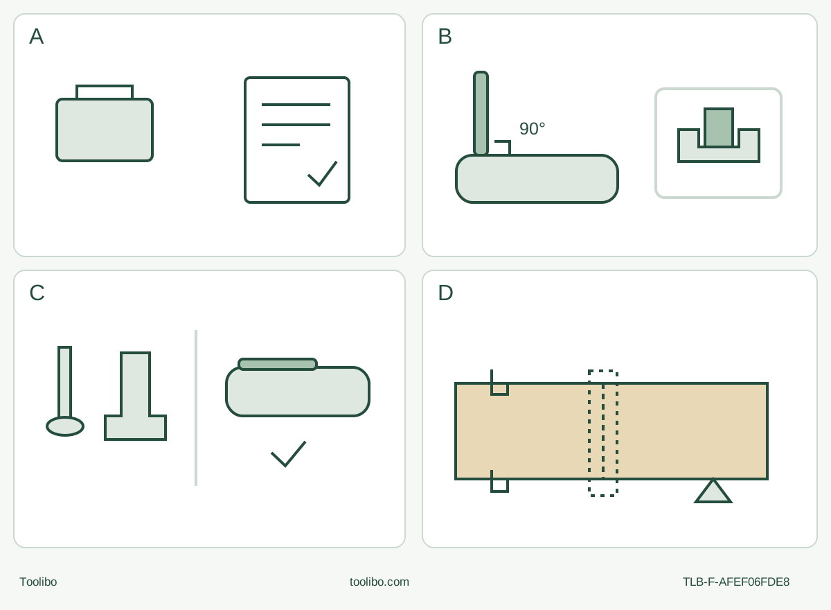
A · Isolate actual power
OFF/full stop/front release and pack out. Match original body,08/24 document, HCS blade and commissioned power.
B · Engage before turning
Lift lever90°, rotate crossbar fully into groove and flip remaining travel before counterclockwise rod loosening; remove old cooled/gloved blade.
C · Tighten and return home
Clean and align all ribs/grooves. Insert/press rod and turn engaged lever clockwise; return perpendicular, rotate and press home to click. Check isolated retention.
D · Finish the whole sample
Qualify dust/PPE and complete support envelope; full speed before contact and full stop before withdrawal. Battery out, cool and inspect both faces.
Original schematic, not scale or counted interface geometry. B still requires rotation into full groove engagement and flipping the remaining lever travel before counterclockwise loosening. C requires all ribs/grooves seated, inserted rod pressed during clockwise tightening, then lever perpendicular, rotated and pressed home to click. D gives no grip, port or depth guarantee.
Match the lever-and-crossbar body before choosing the job
The SKIL OS5920B-00 uses a lever that must engage a groove before it can turn the locking rod. It is not the procedure for every SKIL oscillating tool. Match the actual US body, its controls and original hardware to the linked manual marked 08/24. The OS5920B-10 listing is not a second physical tool to count or proof that every loose kit component is suitable.
This project completes one short straight cut in dry, clean, uncoated loose wood using the positively identified original HCS wood plunge-cut blade. Page 16 establishes wood use for that accessory class; it does not establish a universal-fit claim, a replacement SKU, a numerical accessory rating or a cutting-depth guarantee. Confirm the actual original blade, intended material, secure interface and usable reach against the whole sample. If any of those cannot be established, hold the project rather than testing an unknown blade under power.
Choose a sample that can be clamped, supported and inspected on both faces. The result must be a complete separation on the intended line, not a partially cut bridge or an unseen installed-wall repair. No hypothetical sample size overrides the actual blade, fixture or control limits.
Start with an already qualified power system
The manual rates the body at 20 V DC and lists permitted battery packs and chargers on page 11. This route uses an existing BY519701 battery and SC535801 charger only when the actual pairing has already been correctly commissioned under their own complete instructions. Those two names appear in the tool’s table; the table does not supply a charging tutorial, prove the condition of an unknown pack or authorize every similarly labelled battery. Keep the actual battery and charger safety instructions available. An incomplete, damaged, modified or uncertain power system is a stop condition.
Tool working temperature is −10–40 °C; recommended storage is 0–40 °C. Neither is a charging-temperature recipe. Keep the tool, pack and charger dry and do not allow fluid inside. Protect removed battery terminals from metal objects. No battery service, opening, disposal or transport procedure is supplied here.
Before adjustments, pull the slide switch backward to OFF, wait for complete standstill, press the release button on the front of the battery pack, pull the pack out and remove it completely. An OFF switch alone is not isolation. Keep the pack out during all mounting, fixture changes, inspection and cleaning, and when carrying the tool at your side.
Prepare the whole cutting envelope
Read the actual safety instructions and work alert in a clean, well-lit, dry area without explosive atmospheres. Keep children and bystanders clear and maintain stable footing. Inspect the isolated housing, soft grip, switch, lever, rod and visible original hardware. Missing or damaged parts, an unreliable switch, binding or unexplained looseness must be corrected by qualified service before use; do not use a live trial to diagnose them.
Inspect the wood and both faces of the cut route for nails, screws, coatings, contamination and unknown inclusions. Clamp the retained portion to a stable support. Support the waste separately without closing the kerf or preventing the intended separation. Do not hold the sample by hand. Check the full moving-blade and underside envelope, tool-body travel, rear sideways movement and hand access. Move any support that occupies the cutting path before power is fitted.
Use eye protection marked ANSI Z87.1 with side shields and a full face shield when needed, hearing protection, protective gloves and appropriate dust protection. The cutting instructions require gloves as well as sharp, undamaged blades; gloves are not protection from intentional contact with moving teeth. Keep clothing, hair and hands away from moving parts and vents.
Work with ventilation and approved protection suitable for fine wood dust. Where dust collection facilities are provided, they must be connected and properly used. This manual supplies no native saw-blade shroud or model-specific hose installation: do not invent one or treat a nearby hose as proven capture. Qualify the actual task dust controls, or hold the cut. Remove the tool battery and isolate the extractor under its own instructions before connections or adjustments; any required collection must be correctly connected, operating and checked under those instructions before cutting. A short sample does not remove these requirements.
Engage the crossbar before loosening the rod
With OFF established, the pack removed and the old accessory cooled, wear protective gloves. Keep the rod from facing downward during removal so the accessory cannot fall unexpectedly.
- Lift the clamping lever 90°, perpendicular to the tool.
- Rotate it until its crossbar is aligned with and fully engaged in the groove. The rod can only be loosened or tightened with that engagement established.
- Flip the lever the rest of the way, keeping the crossbar engaged, then turn the lever counterclockwise to loosen the locking rod.
- Remove the old accessory using this released original assembly. Do not stack the new blade over it. Keep the original rod and hardware identified; no extra washer, adapter or replacement-by-appearance is authorized.
This is not a fixed 90° rod-turn instruction. The 90° value above is the initial lever lift. Do not substitute the 140° or 150° lever procedures of other bodies.
Clean the original locking rod and drive shaft. Inspect the chosen blade for cracks, deformation, bluntness or other damage and reject suspect accessories. Position it on the shaft so all accessory grooves match the shaft ribs. The manual permits orientation in 30° increments, but explicitly prohibits a blade facing backward. Choose an unobstructed forward cutting direction for this sample; an available angle does not prove a safe hand or support envelope.
Insert the locking rod into the shaft, press the rod and turn the engaged lever clockwise to tighten the rod. Then bring the lever perpendicular again, rotate it to the position where it can return to its original position, and press it home until it clicks. Keep fingers clear of lever/body and rod/shaft pinch zones while controlling the lever firmly. Verify correct, secure accessory attachment while the battery is still out. If engagement, tightening or the final home position is uncertain, stop; do not force a closure or test it by running the tool.
Select speed without confusing adjustment with cutting
The dial runs from 1, slowest, to 6, fastest. The specification gives 11,000–17,000 oscillations per minute, not a table of intermediate dial rates. Page 17 calls for a medium-to-high initial plunge range; page 12 calls for a scrap trial to determine a suitable setting. Use the same known wood and equally qualified support, dust control and blade clearance. No exact dial number or cutting depth is invented here.
The manual permits adjustment while OFF or running at no load, with the tool controlled in its soft grip. This project chooses OFF, full stop and battery removal for changes as a conservative workflow, rather than asking the reader to adjust while running. Do not claim this choice is an OEM prohibition of its no-load option.
Recheck OFF, secure original holder, fixture and dust controls. Align the pack rib with the tool groove and slide it on until the latches properly engage; check secure attachment without starting. Hold the actual soft-grip barrel as Figure 9 shows, with the other hand away from the blade, work and underside. Do not invent an auxiliary handle or cover the vents.
Cut, stop in the work and inspect the result
With the blade clear, push the slide forward to ON and let the tool reach its full selected speed before contact. Approach the marked route under control and let the blade work without force. While its teeth remain in the work, the manual allows slow sideways movement of the back of the tool to help the cut. Keep that motion within the established clearance; do not twist a trapped blade or use it as a lever.
If the stock shifts, the cut closes, the accessory loosens or noise/vibration becomes abnormal, stop and remove power before assessment. Do not keep pushing to make a protection feature operate. Complete the separation without catching or restraining the waste by hand.
Pull the switch backward to OFF. Page 18 requires complete standstill before removing the tool from the workpiece. Withdraw on the clear path only after that stop, set down safely and remove the battery. Allow the blade and cut surfaces to cool before handling, and keep clear of sharp edges.
Inspect both faces: full breakthrough, intended line and size, no uncontrolled tear-out or scorching, no damaged retained material and no evidence of shifted support. Accept only the complete intended result. Otherwise reject the sample and correct the isolated setup before another attempt; a remaining bridge is not permission to pry or snap it with the blade. There is no invented numerical finish tolerance.
Treat indications and service as separate decisions
The LED work light follows the ON/OFF switch. Rapid flashing accompanies overload/heat protection; slow flashing indicates low charge. Neither pattern is a seating test or permission to continue a suspect cut. Switch OFF and isolate before checking conditions. The manual permits rest or separate airflow cooling for an otherwise sound system; any damaged, modified, insecure or unexplained condition remains a service hold. Low charge goes back to the actual battery and charger instructions, not an improvised charging procedure.
Remove the pack for cleaning. Keep vents and switch free of debris without inserting pointed objects; avoid solvents that damage plastic. If using the manual’s compressed dry air cleaning option, wear safety goggles. Store indoors away from children and corrosive agents within the documented storage conditions. Internal repairs and switch replacement belong to authorized service.
The complete operating evidence is English pages 1–20 of the 08/24 manual, especially power 11, controls 12–13, crossbar/rod mounting 14–16 and wood plunge 16–18. The current product and owner-card links establish the exact document chain, not a new kit, charging or compatibility promise. The owner index is the same underlying index used for other exact SKIL cards, not another unique document or tool.
Models referenced