
The center stays supported until isolation
A shows a marked loose panel, waste-side dashed approach, center waste and an OSP114F entry. B shows retained and waste pieces supported away from two successive blade paths, then OFF and pack removal.
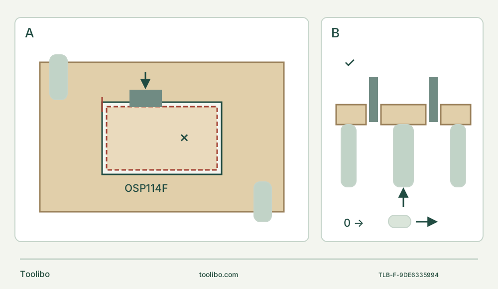
A · Mark and qualify all four sides
Check actual blade width, reach and both-face corner boundaries before any cut. Keep the path on the waste side and never twist an engaged blade through a corner.
B · Support separation and isolate acceptance
Keep center waste independently supported and all blade travel clear. After OFF, full stop and complete pack removal, inspect size, breakthrough, corners and damage on both faces.
Original schematic, not to scale. Dashed line is not a fixed allowance and the central cross is not a hand position. B depicts two successive cut locations, not two blades at once. Its supports must clear the complete actual blade path; the upward arrow marks support under waste, not hand catching. The 0 and pack cue requires complete stop and both-stage battery removal before inspection.
Complete the opening with the panel already removed
The project is a rectangular opening in a known, loose, uncoated solid-softwood panel. You can inspect both faces, support the center waste and see what lies below every cut. It is not an instruction to cut into an installed cabinet back, wall, floor or service enclosure. An opening being drawn for a future fitting does not make an installed location safe to cut, and this sample establishes no structural or electrical-installation approval.
Use the exact US Bosch GOP18V-34 with the March 2023 operating instructions and an actual identified OSP114F Bosch blade rated at least 21,000 OPM. The manual’s page 12 includes this BIM wood/metal plunge blade in the wood application row; page 11 allows OSP and OSL families but excludes OSM. A generic table entry for an OSM blade does not overturn that tool-specific exclusion. This project uses clean wood only; it does not rely on the table’s metal wording to permit unseen fasteners.
The completed outcome is an opening checked from both faces against your marked size and corner requirements, with the center removed only after isolation. If the blade cannot complete the required shape without an overrun or loss of support, stop and change the method rather than force this tool to finish.
Inspect and mark before fitting a battery
Confirm the actual panel material throughout. Reject unknown coatings, treated stock, embedded hardware, loose laminations or uncertain hidden contents from this route. Inspect the full underside and all edges. Measure the panel and opening you actually need; no example in this article supplies a manufacturer cutting-depth rating or a minimum remaining border width.
Mark the finished rectangle and clearly identify the center as waste. Arrange the cut on the waste side so the blade does not consume retained material. Check actual blade width and usable reach against the narrowest part of the opening, every corner and the panel thickness. Include the entire oscillating path, accessory holder and body clearance. The tool’s nominal speed or the blade’s printed family does not prove it can reach through your sample.
Plan each straight side as a separate controlled cut. Do not plan to turn a moving blade through a right-angle corner. If the actual blade is too wide for a short side, or full penetration would overcut a corner on either face, the proposed opening is not suitable for this blade. Do not bend the blade, enlarge its mounting opening or bury the holder to obtain more reach.
The drawing’s outer outline is the intended finished boundary; the dashed inner outline denotes the waste-side approach, not a fixed measured offset. Use actual geometry, not the drawing’s proportions. The center cross marks waste, never a hand position.
Make the final separation safe before the first cut
Clamp the retained panel to a stable work platform. Support the center waste independently so it cannot drop, pivot into the blade or tear the remaining corner as the final connection is severed. Supports must be outside every planned blade path and leave visible clearance beneath the cut. Do not place a hand underneath to catch the center.
Walk through the complete sequence with power removed. Check where the clamps, supports, tool body and both hands will be for all four sides, not just the easiest first plunge. A support that is clear of the first line may obstruct the next. If you must reposition anything, the sequence must include OFF, complete stop and battery removal before moving it, followed by a new full clearance check.
Keep the central piece supported throughout. Do not use the attached blade as a lever to break the last fibers. If a free center could escape the support arrangement or pinch the blade, redesign the workholding before starting. The side-view drawing shows two successive cut positions, not two blades installed or operated at once.
Install the exact accessory while isolated
Slide the switch completely backward to 0 and remove the battery. Removal has two stages: press the pack release and slide forward, then press again and slide completely out. A partly released battery held by the secondary latch is not full isolation. Let a used blade cool and wear protective gloves for handling, changing accessories and work.
Inspect the blade and holder. Do not use dull, bent, cracked or otherwise suspect accessories. With the pack out, remove an existing accessory by opening the release lever; it is released and ejected. Prepare a safe clear landing area rather than catching hot or sharp teeth.
For installation, orient the accessory so its model number faces the tool’s holder. Choose a forward or permitted left/right angle that gives the planned access. Press the tool into the accessory until its clamping jaws snap into it. The manual explicitly says opening the release lever first is unnecessary for installation. Verify that the accessory is securely held while isolated. No screw, extra washer, torque setting or adapter belongs to this snap-in procedure.
A blade that does not seat correctly is a stop condition, not a reason for a powered wobble test. Clean mating surfaces with a clean cloth as necessary; damaged or missing holder parts require qualified service. This article does not authorize opening the tool or repairing the clamp.
Qualify power and make a separate scrap trial
Use only an already commissioned, undamaged Bosch or AMPShare system approved by the exact GOP18V-34 instructions and its March 2023 battery/charger list, with the actual pack and charger instructions available. That list includes BAT612, GBA18V40, GBA18V80 and GBA18V120 packs, and lists the permitted charger models separately. This is not a charging tutorial, a claim that every 18 V pack fits, or a current-kit promise. If you cannot verify your actual system, pause.
Wear eye and hearing protection, protective gloves and appropriate respiratory protection for wood dust; keep the area ventilated and others clear. Establish secure footing, clear lighting and room for both hands. Keep hands away from the blade and out from under the panel. Leave the tool’s vents unobstructed.
With the switch at 0 and the setup ready, slide the qualified pack fully into place until it locks audibly, then confirm it cannot dislodge without the release button. If it moves or comes free, correct the insertion as instructed; never work with a partly latched pack.
Know the three switch positions: first forward is worklight only, second forward I powers tool and light, and fully rearward 0 switches both off. Do not stare into the light. The light-only position is not the isolation used for assembly.
On a separately clamped scrap of the same material, establish the entry and feed. The manual specifies medium speed for initial plunge control, then allows an increase after the initial cut. It supplies no exact numeric initial-plunge dial setting for this sample. The six-position table is approximate: 10,000, 13,000, 14,000, 16,000, 18,000 and 20,000 OPM. Accessory rating must still be at least 21,000 OPM. A dial number is neither a depth nor a length setting.
Cut the four sides without twisting through corners
Hold the tool securely with both hands, accessory away from the body and hands clear. Start with the blade clear, select the powered I position and approach the marked waste-side line under control. Use light pressure and repeated passes, removing a little material at a time instead of forcing the full depth in one plunge. Keep the tool aligned with the straight cut; do not twist an engaged blade to follow the next side.
Stop at the planned endpoint without extending into retained material. Before a new entry, any angle change or support repositioning, switch to 0, wait for complete stop and remove the pack. Recheck the underside and support, then proceed only if the next side is still accessible and clear. The central waste remains supported through the last separation.
Strong vibration, binding, movement of stock, unexpected resistance or loss of visibility means stop, wait and isolate before investigating. Do not increase force or repeatedly restart. If the tool automatically shuts down under temperature/load protection, switch it off and allow the battery to cool as instructed; correct the load problem before considering another attempt. Cooling is not permission to resume an unresolved binding cut.
Isolated acceptance on both faces
After finishing, switch completely to 0, wait for the blade to stop and remove the battery in both stages. Only then remove the supported center. If it remains connected, do not tear or pry it out: inspect the remaining connection while isolated and decide whether a supported permitted cut can finish it without damaging the boundary.
Measure the opening and compare its line and corners on both faces with the actual requirement. Verify full breakthrough and reject unintended corner overruns, major tear-out, scorch marks, shifted supports or split retained borders. The illustration’s check mark means the support concept is appropriate only when all these actual conditions are met; it is not dimensional certification.
If the opening is incomplete or too small, isolate and reassess the precise remaining path rather than shaving blindly. If it is oversized, split or overcut, further cutting cannot restore the lost material: reject the sample or seek an appropriate redesign. No invented tolerance makes a damaged opening acceptable. Store the cooled, isolated tool and accessory safely after cleaning without probing vents or disassembling internal parts. The job ends with a verified opening or a clear stop decision, not merely the center falling out.
Models referenced