
Plan view and thickness check for a three-cut notch
Two panels: upper plan shows an open-edge waste area with two side cuts and an inner cut, retained-side clamps and three conceptual support locations; lower view prompts a separate stock-thickness check.
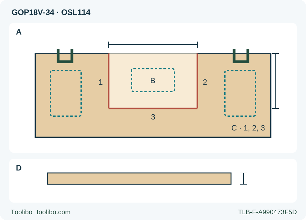
A/B/C · Plan all three cuts and the waste support
Mark retained boundaries and the waste-side kerfs. Verify actual OSL114 width, reach and sweep before cutting sides 1 and 2, then connecting line 3; keep the waste stable and do not turn the blade in a kerf.
D · Check thickness and the finished result
With the battery removed, verify full through-cut access and clear underside. After cutting, isolate again and accept only connected cuts, intended dimensions and waste release without prying or torn retained fibers.
Original project schematic, not to scale and without rated dimensions. Upper A shows the layout; B is support beneath the waste, while C identifies cuts 1, 2 and 3. Dashed supports must actually clear the entire blade path. Lower D reminds you to check real thickness and breakthrough clearance with the battery removed. The diagram does not show a depth stop or authorize cutting a support.
The outcome: an open notch, not an installed opening
An edge notch is complete only when its two side cuts and connecting inner cut meet through the stock, the waste releases without prying, and the retained edges meet the intended layout. This project uses a loose, untreated solid-softwood board and the US Bosch GOP18V-34 with an actual Bosch OSL114 HCS wood plunge blade. Both faces, the open edge and the full blade path must be accessible. It is not a method for notching a structural member, an installed floor or material with hidden services.
The workholding and cut order below are a project plan derived from the manual’s clamping, wood-plunge and no-twist instructions, not a manufacturer-issued dimensional recipe. The diagram deliberately gives no notch dimensions or stock-thickness rating. Choose a sample whose actual thickness, notch width and setback can be reached by your identified blade without the tool, holder or teeth contacting retained material outside the intended cut. If that cannot be established with the battery removed, choose a different geometry or tool.
Confirm the exact system before drawing the cut
Use the actual US GOP18V-34 and matching March 2023 instructions 16099221RZ. It accepts the listed OSL and OSP families, not OSM. The shared accessory table includes OSM114, but that row does not override the model’s interface exclusion. This project selects OSL114, whose HCS wood row expressly includes separating and plunge cuts in wooden material. Use the actual Bosch accessory rated at least 21,000 OPM; the tool’s maximum is 20,000 OPM. A rating is not a command to start at maximum speed or a promise of compatibility for a similarly shaped blade.
The power prerequisite is an already commissioned Bosch/AMPShare 18 V system approved by the matched battery/charger list and the actual pack and charger instructions. The list is compatibility evidence, not a complete charging tutorial. Do not proceed with an unidentified, damaged, modified or unapproved battery. This project introduces no new power pairing or kit-content claim.
Slide the switch fully backward to 0, wait for any movement to stop, then remove the battery completely. This pack has two retention stages: press the release and slide forward, then press again and slide fully out. The intermediate light-only switch position is not OFF and neither OFF nor a dark lamp replaces physical battery removal for setup.
Lay out the retained boundaries and the waste
Mark the two side boundaries from the open edge to the intended inner boundary. Mark the connecting inner line, and transfer the layout to the opposite face so breakthrough can be checked while isolated. Clearly identify the retained area and waste. Plan the kerf on the waste side of each finished boundary; centering a finite-width cut on a finished line removes material from both sides of it.
Check the actual blade’s working width, usable reach and oscillating envelope against all three cuts. For the inner line, there must be room to place and advance the blade without its corners crossing either retained side boundary. A wide plunge blade cannot produce an arbitrarily narrow rectangular notch simply because its teeth can enter the wood. Do not bend it, twist it or angle the tool to hide an oversized swept path. No nominal blade dimension substitutes for this isolated access check.
Select straight, sound stock with no fasteners or foreign material in the full path. Do not use coated, pressure-treated or unidentified demolition wood for this exercise. The open-edge layout avoids a trapped internal plug, but the waste can still move or pinch the blade if its support is neglected.
Support the board and the waste independently of your hands
Clamp the retained board to a stable platform on both sides of the notch. Place supports under retained stock, clear of every planned cut. Arrange a separate stable support for the waste, also clear of the complete through-cut path. It must not push the waste into the blade or require a hand under the cutting area. A loose block that can tip or shift is not adequate support.
Inspect from both faces with the battery out. Check the entire blade depth and sweep beyond breakthrough, the clamp positions and the approach needed for the inner cut. If a support must move between cuts, that is a stop-and-isolate operation, followed by a fresh clamping check—not a movement to make while the blade runs. The diagram’s dashed rectangles are conceptual support locations, not guaranteed clearances or hidden objects that may safely be cut.
Provide good light and dust control for the known material. Wear eye and hearing protection, suitable dust protection and the manual’s protective gloves. Keep other people away, handles dry, vents clear and both hands on the tool’s proper gripping areas. Do not put fingers beneath the board or in front of the blade. The work light improves visibility but cannot reveal concealed hazards or establish underside clearance.
Install the wood blade with the battery still removed
Inspect the blade and holder for damage and contamination. Clean their contact surfaces with a clean cloth as necessary. A cracked, bent, dull or uncertain attachment is a stop for replacement or service, not a candidate for a powered fit test. Allow a previously used blade to cool before handling.
Orient the accessory so its model-number face points toward the holder. Choose the allowed orientation that gives a clear approach and preserves a firm two-hand grip. Press the tool into the accessory until the clamping jaws snap into it. The release lever does not need to be opened for installation. Check that the accessory is firmly seated before proceeding.
To remove or reorient it, remain isolated, open the release lever and anticipate that the accessory is released and ejected. Keep its sharp or hot edge away from hands and provide a safe landing area. Reinstall with the complete snap-in procedure; do not treat a partly engaged blade as usable because its teeth look aligned.
Make the side cuts, then connect them without turning the blade in the kerf
Confirm 0 before reinstalling the qualified battery and verify that the pack locks securely. Start with the blade clear. The switch’s first forward position lights the work area; the second, I, runs the tool. The six-position dial spans approximately 10,000–20,000 OPM. For initial plunge, the manual says to begin at medium speed for control and allows an increase after the initial cut. It does not give a precise numbered setting for this notch. Practise on matching scrap and follow the actual blade’s instructions.
Cut the first side boundary from the open edge toward the inner line with smooth, light passes. Keep the blade in the intended plane. Remove only a little material per pass and stop at the marked intersection rather than running beyond it. Repeat for the second side with the waste still supported. Do not rotate the tool through a corner while the blade remains in a narrow kerf: the manual expressly warns against twisting because it can bind the blade.
Stop, wait for standstill and remove the battery before checking the underside, changing your approach or reorienting the accessory. Confirm that each side cut reaches through the intended thickness without overshooting the retained boundary. If completion is uncertain, inspect and make a controlled additional pass only after the setup is requalified; never probe beneath a moving blade.
For the connecting inner cut, keep both retained areas and the waste stable. Align the actual blade within the waste-side boundary, begin the plunge under control and connect to the completed side cuts with shallow progressive passes. Where the blade width requires more than one placement, stop and isolate before repositioning the setup. Do not use the blade as a chisel or lever to snap the last fibers. If the waste remains attached, the cut is incomplete: locate the remaining connection with the tool isolated and plan another controlled pass rather than pulling it free.
Stop for a changed setup, not only at the last line
Stock movement, binding, abnormal vibration, smoke, unusual heat or any loosening accessory requires stopping. Slide fully to 0, wait for complete stop and remove the pack before investigation. Do not restart repeatedly to overcome a trapped blade or use more pressure to compensate for a blunt one.
The model can reduce speed or shut down under thermal/load protection. For an automatic shutdown, switch OFF and allow the battery to cool as the manual directs; correct the load problem before any restart. Protection is not a licence to keep forcing the cut. Damage or persistent unexplained behavior belongs with qualified service, not battery repair or a running fault test.
Inspect the notch while isolated
After the final cut, stop the tool and let the blade become stationary before placing it safely down. Remove the battery before clearing the waste or checking the edges. The waste should now separate without prying or tearing away retained fibers. Keep clear of the blade until it has cooled.
Check both faces: the three cuts must meet, the intended notch must be through, and its width and setback must match your layout requirements. Reject an overrun into the retained board, split corner, scorched edge, major tear-out or evidence that the work shifted. The article gives no invented tolerance or structural acceptance standard. If a nonstructural trial piece is too small or damaged, remake it; do not conceal the error by calling the notch “close enough.”
Minor edge cleanup is a separate isolated operation, not an excuse to rock the powered saw against the corner. Clean the exterior and holder as instructed, store the removed battery safely and retain the sample only as evidence of this specific layout and setup. A successful notch in loose stock says nothing about the safety or strength of a similar cut in a building component.
Source basis: GOP18V-34 instructions 16099221RZ, March 2023, safety pages 2–5, identity 8, assembly 9, controls/power/interface 10–11, exact wood-blade row 12, cutting 16 and actual no-twist figure 18; matched battery/charger list 1600A02TM0. The project layout is an explicit application of those limits, not a manufacturer capacity specification.
Models referenced