
Three checks, one decision
A shows a neutral blade silhouette and conditional check. B separates supported retained stock and waste around a clear path. C shows a square used only for isolated sample acceptance.
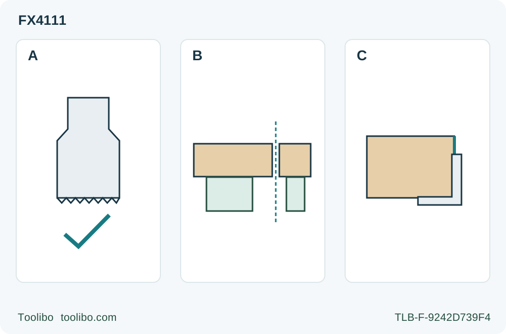
A · Identity before replacement
Confirm exact permitted accessory, rating, material and sound condition. A check mark is conditional on all of these, not its silhouette.
B · Correct the supported path
Clamp stock, support waste and keep the complete oscillating path clear without pinching. Do not compensate for movement with more pressure.
C · Inspect the isolated result
Judge line, size, separation and surface against the actual project. Persistent unexplained poor cutting means service, not repeated powered trials.
Original schematic; A does not depict the mounting interface or certify a blade. B omits clamps for clarity, not permission to omit them; establish actual clamping and full clearance. C is a measuring square after OFF, full stop and battery removal, not the optional FLEX edge guide.
A poor cut is a reason to stop, not to push harder
This guide addresses a previously observed slow, wandering or rough cut with the US FLEX FX4111 on known, loose, uncoated solid softwood. Its outcome is a decision: correct a documented external setup problem and make one properly prepared sample, or leave the system out of service with useful evidence. It is not a motor diagnosis, an instruction to reproduce a fault under power, or permission to cut an installed wall or unknown reclaimed board.
Move the switch rearward to OFF, keep control until the accessory stops completely, and remove the battery with its front release button. Let hot parts cool. Wear protective gloves for accessory changes; do not touch moving teeth. Do not insert a pack merely to see whether a loose blade wobbles. A failed switch, damaged holder, missing part, burning smell or unexplained repeated interruption ends this exercise: keep the tool isolated and contact an authorized service provider.
The source is the FX4111 operating manual, especially safety pages 3–5, assembly 9–11, controls 12–14, accessory table 15, cutting 17 and maintenance 20. The checks below apply its instructions to this limited project; they do not establish a wear tolerance or certify a used tool.
First separate an unsuitable job from a faulty machine
Write down what actually happened: blade identity, material, whether the work moved, remembered speed level, and any light pattern already seen. Do not recreate the event to complete the record. A slow cut alone does not identify a weak battery or failed motor. Nor does a bright work light prove useful battery capacity.
For this route, identify an actual FLEX FA401002 HCS curved plunge blade approved in the manual for wood and plastics, and confirm its rating is at least 20,000 OPM. Inspect its markings and condition while isolated. A vaguely similar tooth shape, a matching-looking socket, or a general Starlock advertisement is not enough. The manual’s broader compatibility discussion does not override its assembly warning to use FLEX accessories meeting that rating. This article does not approve an unmarked substitute.
Reject a bent, blunt, broken or otherwise damaged blade. Do not straighten it, grind a new mounting opening, add a washer or prescribe a sharpening method absent from the instructions. Replace it with an identified, undamaged approved accessory. A visual check can reveal a problem, but cannot prove that a suspicious blade is sound.
Inspect the complete workpiece, both faces and the exposed underside. Unknown coatings, hidden fasteners, embedded grit, laminates or uncertain material take it outside this clean-wood task. Confirm actual blade reach and space for its entire oscillation without contact with the holder, bench, supports or clamps. If a safe path cannot be arranged, choose another method rather than blame cutting speed.
Re-establish the documented attachment, with the battery out
If accessory identity and condition pass, check the exact holder procedure rather than inventing a tighter setting. With OFF confirmed and the pack removed, turn the release lever counterclockwise past the first click, then through resistance to the second click at its full travel. The manual calls the jaws CLOSED in this accessory-change position. On removal the accessory can fall out: prepare a safe landing area and keep hands away from its teeth, rather than trying to catch a hot blade.
Place the replacement accessory on a flat surface. Hold the machine body and lever as instructed, align the star interfaces, and return the lever clockwise to its original position. The jaws then OPEN and lock the accessory. These words are the model’s actual sequence, not the familiar jaw logic of another clamp. Never install the accessory pointing backward.
Verify secure seating while isolated. If it does not lock as described, the lever cannot return normally, or parts are damaged or missing, stop for authorized service. No extra shims, improvised fastener, guessed torque or powered seating test belongs here. This is the boundary between a documented accessory change and repair of the holder itself.
Correct support before touching the speed buttons
For the trial, select a manageable loose sample whose intended cut and underside remain visible. Mark the required line and size. Clamp the retained piece securely and support the waste so it cannot drop, rotate or close onto the blade. Arrange clearance through the complete cut, including breakthrough. The schematic support blocks are not clamps: actual clamping and clearance must be established on the bench.
A wandering cut may follow shifting stock or a pinched kerf. Fix those conditions while isolated; a higher speed is not their remedy. Do not hold the work by hand, lever the blade sideways to recover a line, or pull the tool against a binding cut.
This basic trial does not require the optional edge guide. If the existing setup used one and its geometry cannot be verified, remove that attachment while isolated and choose a supported free cut with adequate access, or stop. The optional guide is not a substitute for clamping. Its own manual procedure requires secure collar engagement, a separate locked guide setting, clamp clearance and full blade engagement throughout oscillation. Do not approximate that setup from the small acceptance-square drawing.
Decide whether a controlled sample is justified
Proceed only if the actual 24 V DC body is undamaged and its existing power system has already been commissioned against the manual’s listed packs and chargers, with the actual battery and charger instructions available. Page 13 lists FX0111, FX0121, FX0221 and FX0231 packs, and FX0411 or FX0421 chargers. This is a qualification gate, not a new pairing or charging tutorial. An unidentified, damaged or unsuitable power system means stop.
Use eye protection with side shields or goggles marked ANSI Z87.1, and a full face shield when needed, plus hearing protection and protective gloves and the dust protection required for the material and conditions. Keep people clear, establish stable footing and a clear view, and keep hands out of the cutting path. With the switch OFF, align the pack rib with the tool grooves and latch it properly. Do not force a misaligned pack.
Check the actual selected speed while OFF: memory can retain a previous setting. The manual specifies level 3 for initial plunge control; only after establishing that cut may speed be increased. Its approximate levels are 10,000, 12,000, 15,000, 18,000 and 20,000 OPM. These are not removal-rate guarantees. Make any change with the tool OFF for this project, never while its teeth are engaged.
Hold the soft-grip area securely with both hands clear of the accessory. Move the switch forward to start and approach the marked cut under control. Use light feed and let the tool work. Strong vibration during the plunge indicates excessive pressure according to the manual; do not answer it with more force. If the sample shifts, the blade binds, the cut behaves unexpectedly or control is lost, switch OFF, wait for complete stop and remove the battery before investigating. Do not keep repeating trials until the symptom disappears.
Accept the sample—or prepare a service handoff
After the trial, switch OFF, wait for the accessory to stop and remove the battery before measuring or touching the cut. Check the intended line and size, complete separation and the surfaces on both faces. Reject unintended wandering, substantial tear-out, scorching, shifted support or incomplete breakthrough. There is no invented numerical tolerance: judge against the actual project’s requirements, not this drawing.
A clean acceptable sample after a clear, documented setup correction supports continuing that same qualified setup. It does not prove the machine has no internal fault. If poor results persist without an identifiable permitted correction, stop. Record the exact body and blade markings, material, setup photographs taken with power removed, selected level and observations; give these to authorized service. Do not open the housing or adjust internal parts.
Treat previously observed signals separately. The work light’s roughly ten-second afterglow is normal; rapid flashing concerns overload or heat, while slower flashing concerns low battery. For overload or heat, OFF and isolation come first; rest the system or cool tool and battery separately under airflow as the manual describes. Charging must follow the actual pack/charger instructions. A light that fails to illuminate or suddenly goes out calls for customer service or an authorized center. None of these signals authorizes bypassing protection or repeatedly restarting a failing cut.
Keep vents and switch areas clear without probing openings with pointed objects or using plastic-damaging solvents. Store the isolated tool indoors away from children and corrosive agents. The complete result is either a verified external correction and acceptable sample, or a stopped, documented system ready for qualified help—not a guessed diagnosis.
Models referenced