
Three checks before the first cut
Three panels show two release-lever clicks and an accessory approaching the holder, five speed levels with level 3 highlighted, and a clamped wood sample with a level-3 plunge.
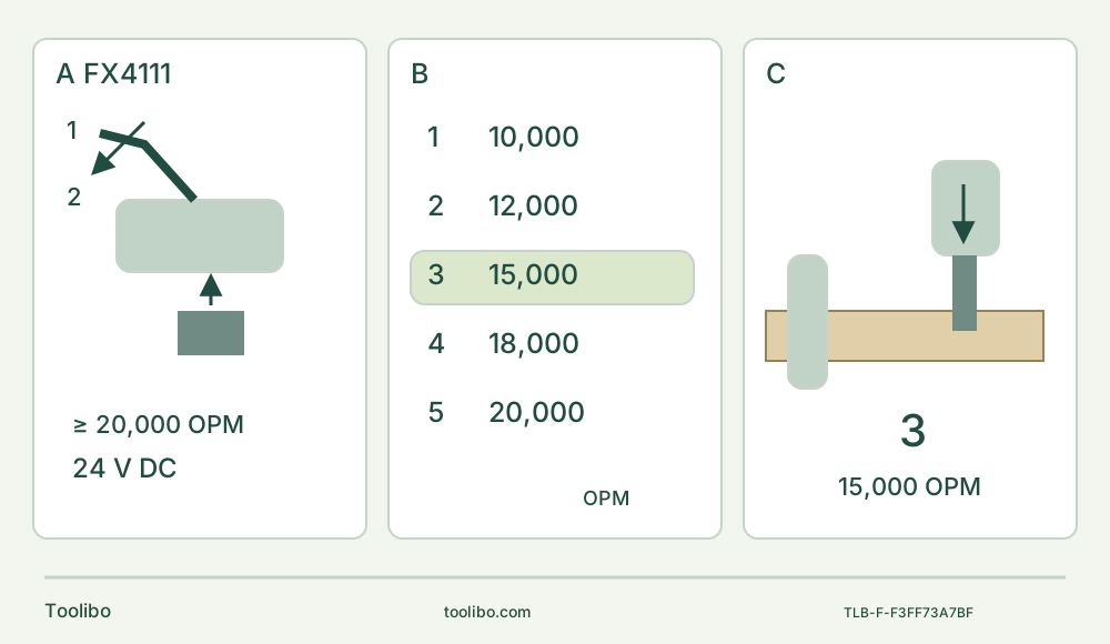
A · Isolate and complete the clamp
Battery out and OFF: turn counterclockwise through two clicks; jaws close for changing. Align the accessory and turn clockwise to the original position so the jaws open and lock it. Never face it backward.
B · Verify the remembered level
The five approximate levels run from 10,000 to 20,000 OPM. Change only OFF or unloaded, never in the cut; memory may retain a previous high setting.
C · Start at level 3
Use approximately 15,000 OPM for the initial plunge into secured known wood. Keep both hands clear of the blade and preserve support and clearance through the whole cut.
Original schematic freshly compared with the linked manual. A shows accessory placement, not battery insertion or exact jaw geometry. Battery removal, full clockwise locking and two-hand control remain mandatory; C is not a complete work-support drawing.
Start with an identifiable owner system
This is a first controlled wood-cut project for an existing US FLEX FX4111, not a test report or a promise about today’s kit contents. Match the body and controls to the official FX4111 manual linked from the current manufacturer product page. FX4111-1A and FX4111-Z are configurations of the same tool here, not two different machines. The downloaded manual has no identified printed revision date; a date embedded in another filename is not a verified revision.
The project uses a loose, known, unfinished softwood sample, visible on both sides and secured on a bench. It does not authorize a plunge into a wall, floor, installed trim, unknown coating or concealed services. Choose a short cut that leaves the blade and its entire movement clear of the bench, clamps and hands. If you cannot support the retained piece and control the waste without pinching the blade, change the setup before fitting power.
Qualify the battery before operating the tool
This 24 V DC body is covered here only with an already commissioned, undamaged genuine power system explicitly listed in the matched manual: FX0111, FX0121, FX0221 or FX0231 battery, and FX0411 or FX0421 charger. Read and retain the actual pack and charger instructions and verify the exact physical labels. A marketing statement about a platform is not permission to substitute an unlisted or modified pack. This article does not establish a new charging setup, charger supply rating or charging temperatures. If the pair has not already been qualified, stop at that gate.
Inspect the tool, battery, switch, holder and blade for damage or missing parts. A defective switch or insecure holder means service, not a trial cut. Keep terminals away from loose metal and do not use damaged or modified batteries. The tool manual’s operating range of −20 to 40°C and storage below 50°C do not override separate battery or charger limits.
Move the slide switch rearward OFF and remove the battery for every accessory change, guide adjustment, inspection and cleaning. To remove it, press the release on the front of the pack and withdraw it. OFF alone is not isolation. Later, insert only with the switch OFF, aligning the pack rib and tool grooves until the latches engage securely; do not force a misaligned pack.
Complete both clicks, then lock the accessory
Use an undamaged, sharp FLEX accessory identified for this tool and rated at least 20,000 oscillations per minute. For this known-wood exercise, the manual identifies FA401002, the HCS curved plunge blade, for wood. Confirm the actual blade’s identity and instructions; a similar shape is not identification. Although the product and later manual text discuss broader interfaces, the mounting warning specifies FLEX accessories. This conservative workflow does not grant universal third-party, adapter or Starlock-family permission.
With the battery out and switch OFF:
- Turn the release lever counterclockwise past the first click. That click engages the mechanism; it is not the completed change position.
- Continue through the increased resistance to the stop and second click. The manual calls the clamping jaws closed in this position, ready to receive the accessory.
- Put the accessory on a flat surface. Hold the machine body with one hand and the release lever with the other, and align the star-shaped mating interfaces. Use an allowed working angle, never an accessory pointing backward toward the body.
- Return the lever clockwise to its original position. The jaws open to lock the accessory. Do not reverse these unusual jaw descriptions by analogy with another brand.
- With power still removed, check secure seating and that the lever is fully returned. An accessory that does not seat or retain correctly is a stop condition, not a reason to force the lever or test it under power.
Removal repeats the full two-click counterclockwise movement; the accessory can fall when the jaws close. First let it cool, wear protective gloves for the hot/sharp accessory and arrange a safe receiving surface clear of feet and hands. Do not catch a falling blade by its teeth. A release mechanism does not make the blade cool or harmless.
Decide whether the guide is actually needed
The simple sample cut can be made without a guide. If using the actual complete attachment collar, fit it with the battery removed. Loosen its locking bolt using the hexagonal rod of the depth gauge or edge guide. Align the collar’s four positioning tabs with the neck grooves, seat it, choose the angle and tighten the bolt securely. The separate knob holds the inserted guide; tightening that knob does not replace tightening the collar bolt.
For a plunge depth gauge, set the distance between the blade tip and gauge tip to the required depth. If the blade is angled, rotate the collar so the gauge is parallel to the blade, then secure the collar bolt and guide knob. Check the geometry on the isolated sample. A depth stop does not find wires, allow for an unseen cavity or certify that an installed surface is safe to cut.
For the edge guide, the manual describes its right edge following a straightedge secured to the workpiece. Position and rotate the collar so the blade remains fully engaged with the workpiece throughout its entire oscillation. If either blade edge travels outside the workpiece, the tool can jump. Tighten the collar bolt and guide knob, and check that all clamps clear the tool’s complete travel. This is a distinct setup, not a reason to steer the blade sideways or assume the guide prevents every kick or loss of control. Do not introduce a segment blade merely because the same guide also has a documented segment-depth function.
Set level 3 for the initial plunge
The five levels are approximately 10,000, 12,000, 15,000, 18,000 and 20,000 OPM. The tool remembers the last active setting; switching OFF does not guarantee a return to a gentle starting level. With the work area ready, hands clear and the qualified pack latched, check the selected level before beginning.
Speed may be changed only while OFF or running without load, never while the blade is engaged in the cut. When adjusting a running unloaded tool, keep a firm hold in the soft-grip area and control the free blade. The buttons can wake the panel while the motor is OFF; its lights going dark after inactivity are not proof that the battery is disconnected.
For the initial plunge, the manual specifies level 3 for control. After establishing the initial cut, a higher setting may be selected for faster cutting, but first clear the cut and obey the OFF/no-load adjustment rule. Neither maximum speed nor a numerical setting can compensate for an unsuitable blade, excessive pressure or poor support.
Make and finish the supported cut
Arrange good lighting and a clear stance, keep bystanders away, and wear eye protection with side shields, hearing protection and appropriate dust protection. Address harmful or combustible dust before starting: use ventilation and suitable dust/chip extraction where connectable. Do not invent a blade-capture attachment or treat the worklight as a substitute for room lighting. Keep clothing, hair and hands away from the accessory.
Hold the tool securely at its insulated soft-grip surfaces with both hands, without obstructing controls or placing a hand under the sample. Keep the blade clear at startup. Push the switch forward to run, then make the initial level-3 entry with light, controlled feed. Let the blade work rather than levering or forcing it. Strong vibration during the plunge is a warning of excessive pressure. If cutting stalls, the work shifts or the blade binds, move OFF, wait for complete stop and remove the battery before diagnosing the setup.
Continue only while both sides of the sample, waste support and blade clearance remain controlled. Finish without allowing the waste to tear away or pinch the blade. Move the switch rearward OFF and wait until the accessory has stopped before setting the tool down. Remove the pack after use, then inspect the result and any burr or splinter with the tool isolated. Sanding, grout removal and scraping require their own matched accessory, material and dust assessment; this completed wood cut is not approval for those operations.
Read the worklight correctly and close the job
The worklight normally remains on for about ten seconds after stopping. Rapid flashing indicates overload or excessive temperature of the tool and/or battery; slow flashing indicates low battery capacity. These are not interchangeable with the speed-level LEDs. If the tool cuts out, set OFF and isolate it before investigating. Allow an overheated tool and battery to rest and cool separately under airflow. Do not repeatedly restart to defeat a cutoff or assume the motor cannot restart after a condition clears. A low pack returns to its already qualified charging procedure, not an improvised charger.
If the worklight does not illuminate when starting or goes out suddenly during operation, the manual directs customer service or an authorized service center. Damage, abnormal operation or a fault that recurs after correcting the load also ends the project pending service.
With the battery removed, keep vents and switch areas clear, inspect for loose, damaged or missing parts and avoid pointed probes through openings or plastic-damaging solvents. Leave internal repairs to authorized service using identical replacement parts. Store the tool indoors, dry and inaccessible to children, apart from corrosive agents and with battery terminals protected. Success is a controlled finished cut and an isolated, inspected tool—not merely a blade that moved.
Models referenced