
Lock the pin and classify the sanding system
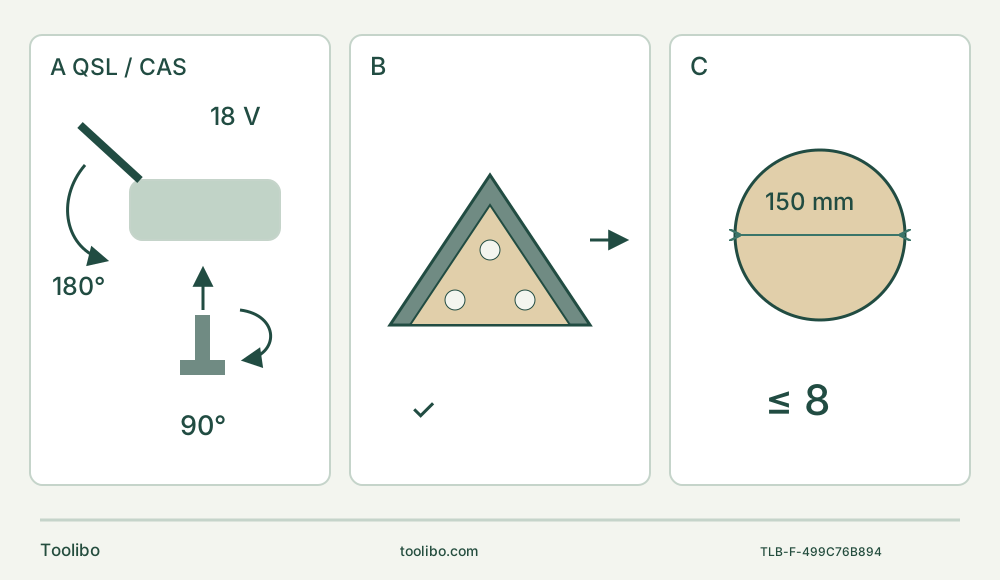
Three panels show the 18 V Q SL identity with 180° lever and 90° pin actions, aligned triangular sanding paper, and a 150 mm plate limited to setting 8.
A · Finish the quarter-turn clamp
Remove the battery, open the lever 180°, turn the pin slightly counterclockwise and remove it. Seat the cams, insert the pin and turn it 90° clockwise; close the lever against the housing.
B · Complete triangular sanding extraction
Fit the extraction body securely on the flange, connect the suitable adapter/hose and align paper holes with the actual triangular pad. Inspect the whole assembly before powering.
C · Keep the large-pad limit separate
A 150 mm sanding plate must not exceed setting 8. The triangular task uses a practical trial within its actual accessory limits, not an invented universal setting.
Freshly reviewed original schematic. A means only the approved commissioned power system, not every CAS pack. B illustrates hole alignment rather than an exact hole count; full extraction is required separately. C is a separate 150 mm accessory limit, not the starting setting for the triangular project.
Match the Austrian Q SL body
This owner project uses the Metabo MT 18 LTX BL Q SL identified by Austrian product 613088840, service selection 13088000 and manual serial family 13088… The matched operating manual is 170 27 6760–0323, read with the current 1025 general safety supplement and the actual supplied instructions. It is not the legacy MT 18 LTX or the corded MT 400 Quick. Similar names do not make their spring-pin movements interchangeable.
The complete task is to smooth a small flat area of a clamped, loose, known, untreated softwood sample with an approved triangular sanding system and suitable extraction. The surface must be dry and visible. Wet coatings, solvent-impregnated surfaces, unknown paint, adhesive removal and installed assemblies are outside this exercise. This is a documentation-based guide, not a hands-on performance test or a promise about current box contents.
Qualify the existing battery and charger
The tool is rated 18 V. Use an undamaged original Metabo or approved CAS battery system that meets the exact tool and power-system instructions, not a generic pack selected only by voltage. For a narrow existing-owner example, the tool manual lists pack 625367000 and chargers ASC 55, reference 627044000, and ASC 145, reference 627378000. Confirm the physical pack and charger labels and their actual compatible instructions. This guide assumes the pair is already commissioned; it does not teach a first charge, specify a charger’s mains input or assert every CAS-branded combination is acceptable.
The tool’s permitted ambient operating range is −20 to 50°C, with reduced performance below 0°C; its stated storage range is 0–30°C. These tool conditions do not override the actual battery and charger limits. Do not use faulty, deformed or modified batteries. Keep them away from moisture, fire and conductive objects, and never open a pack or bridge its terminals.
Inspect the tool, switch, holder, spring pin, pad and battery before starting. Damage, missing parts or a switch that cannot control operation is a stop condition. Move the slide switch backward OFF, press the battery release and remove the pack. Battery removal is required before adjustments, accessory changes, maintenance and cleaning. When inserting it later, keep OFF selected and slide the pack in until it engages securely. Electronic protection does not replace isolation.
Fit only the approved interface and material system
The matched manual permits Starlock and StarlockPlus accessories, not StarlockMax. Use an original recommended accessory satisfying the tool specifications and appropriate for the material. For this exercise, identify a compatible triangular sanding plate and matching sheet from their actual instructions. Do not infer that an adapter or a similarly shaped pad makes an unsupported interface acceptable.
Check the plate, holder and paper for cracks, distortion, wear or contamination. Select a grit suited to the sample and desired finish, with a scrap trial rather than an invented universal grit recipe. The paper and plate holes must align so extraction is not blocked. A worn or insecure sheet needs replacement, not more downward pressure.
The actual mounting sequence is distinct:
- With the battery removed, move the clamping lever forward through 180°.
- Turn the spring pin slightly counterclockwise and remove it.
- Seat the accessory in the desired position on the holder, ensuring the holder cams engage correctly.
- Insert the spring pin and turn it 90° clockwise.
- Close the lever fully to its stop and engage it. The lever must be in contact with the housing.
- Check the accessory for a firm hold while the tool remains isolated.
The lever can spring back and pinch fingers. Wear suitable protective gloves, keep fingers away from its closing path and allow hot accessories to cool. Do not replace the quarter-turn pin action with a guessed screw torque or merely push the pin in without turning it. If the holder will not engage or the lever will not close properly, stop rather than using power to test a doubtful clamp.
Install the complete triangular-pad extraction
The manual specifies this extraction attachment only when working with the triangular sanding plate. It is not a general saw-blade dust hood. Before fitting it, remove the battery and accessory. Place the extraction assembly on the housing flange in the desired position and secure it using the designated screw and screwdriver. Insert the extraction adapter and connect a suitable extractor through the appropriate hose; the actual illustration identifies the 28 mm connection.
Then install the approved sanding plate using the complete spring-pin sequence and align the sanding sheet holes. Verify that the extraction body, hose and fasteners do not interfere with the accessory, grip or planned movement. An incomplete or incompatible dust assembly is not ready simply because a hose can be pushed onto it.
The illustrated depth guide is attached to the extraction assembly with its own screw. If using that actual matched guide, loosen the designated guide screw, set the required depth and retighten it while isolated. It does not prove hidden services are clear, establish a universal blade-depth limit or authorize moving the sanding extraction assembly around a saw blade. The small flat-sanding task does not need a depth-guide claim.
Secure the sample and control the dust
Clamp and support the work on a stable platform. It must not rock, flex or slide under normal sanding pressure. Leave access to the intended surface without allowing the pad to strike a clamp or metal bench part. Never hold the sample in a free hand or against your body. Plan the whole pass and hose route before fitting the battery.
Use both hands on the provided gripping area, stand securely and keep hands away from the accessory and underside of the work. Keep ventilation slots open. Wear protective goggles, suitable respiratory protection and hearing protection as required by the task. Provide ventilation and suitable source extraction; prevent deposits around the bench and avoid directing exhaust toward people or accumulated dust.
The manual advises vacuum cleaning rather than sweeping or blowing settled dust into the air. Clean protective clothing by vacuuming or washing, not beating or brushing it. Material-specific dust hazards still matter with an extractor: unknown hazardous coatings and asbestos are not part of this ordinary wood exercise. Keep bystanders clear and do not stare into the operating LED or inspect it with optical instruments.
Find the sanding setting by a controlled trial
The machine’s no-load frequency range is 8,000–20,000 oscillations per minute, with 1.6° movement to each side. The manufacturer directs a practical trial to determine the setting. This guide does not invent a numbered frequency map or borrow another model’s small-pad levels.
The manual separately limits a 150 mm sanding plate to maximum setting 8. That rule is not a command to start this triangular-pad task at 8 and does not itself approve an unidentified large plate. Respect the actual pad and paper limits and test on the secured sample. Complete the initial setting with the battery removed; do not reach into the accessory area to adjust a running setup.
After the full clamp, dust and support checks, confirm OFF and fit the qualified pack. Hold with both hands, start with the pad clear of the material by pushing the slide forward, and then approach the sample. The forward position is continuous operation: releasing your hand is not a stop method.
Sand with moderate pressure and a controlled back-and-forth movement over the intended area. Do not hold one corner in place or force the tool until the pad catches or the work overheats. If the sample shifts, the sheet detaches, extraction fails or vibration changes abnormally, switch OFF, wait for complete stop and remove the battery before inspection.
Finish the pass, remove contact with the work, move the switch backward OFF and wait for standstill before setting down. Remove the battery and inspect the cool sample in good light. Accept the pass only if the intended area is evenly finished without unwanted rounding, gouging, scorching or evidence of shifted support. Reject a defective trial, correct the accessory, support, pressure or setting, and repeat on a suitable sample. No numerical flatness or finish tolerance is claimed.
Keep three protection signals separate
A flashing LED on the battery’s capacity display indicates an almost-flat pack in the described indicator system; follow the actual pack instructions and its qualified charging process. This is not the same as the tool’s LED worklight flashing while the motor refuses to run.
The latter combination can indicate restart protection: insertion of a battery while the slide switch is ON prevents starting. The manual’s recovery is OFF, then ON. Do not deliberately use that protection as your insertion routine. Always insert with OFF selected, check the setup and only then start intentionally.
Long continuous overload can trigger the temperature cutout. Set OFF, isolate for any physical checks and let the tool or battery cool. The manual notes faster battery cooling in a suitable AIR COOLED charger and faster machine cooling at idle. Those notes do not approve a new charger, force a stopped motor to run, or bypass a cutout. Only an otherwise intact, freely operable tool in a controlled clear position belongs in an idle-cooling situation. Stop for recurring or unexplained faults.
Automatic protection does not prevent every overload; damage remains possible. Do not keep cycling the switch, continue with an insecure accessory or assume protection has electrically isolated the machine.
Store the inspected system
Remove the battery before cleaning or maintenance and vacuum the motor ventilation openings regularly. Keep the holder, lever and grip clean without opening the housing or inserting metal probes. Electrical repairs are for qualified personnel using the proper parts. A damaged battery is not an owner repair project.
Store the clean dry tool and protected battery within their respective permitted conditions, out of children’s reach and with terminals kept away from metal objects. Different work such as sawing or scraping requires another approved accessory, material assessment and support plan. The successful result here is a finished small wood surface, a secure and inspected holder, and a deliberately stopped, isolated system.
Models referenced