
One exact system, three distinct indicators
Four panels show legacy type 13021 with pack 625596000 and a charger, upward pack removal and a fully retained pin, separate tool light, battery indication and charger displays, and a sanding collar secured in position A rather than free region B.
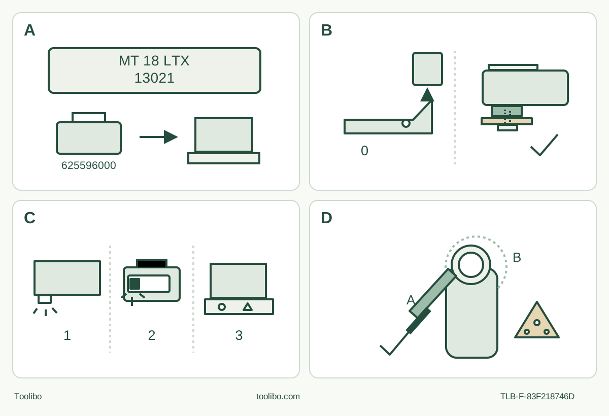
A · Qualify the existing pair
Match original type 13021, battery 625596000 and actual ASC 55 supply and instructions; this is not a kit-inclusion claim.
B · Isolate, engage and lock
Switch OFF, release and pull the pack upward. Engage accessory cams, insert the original spring pin fully and lock the lever against the housing.
C · Locate the signal
The tool worklight can signal restart inhibition; one battery LED means almost flat; the charger has separate temperature and fault displays.
D · Secure sanding extraction
Use the documented anti-twist position A, not free-moving region B; connect the suitable extractor and align the triangular sheet holes.
Recovered original schematic checked against fresh primary figures and the new body. The battery gauge shows one flashing indication without claiming a total LED count; the collar is sanding-only.
Identify the machine before interpreting a light
A flashing worklight on the tool is not the same warning as a flashing capacity LED on its battery. Neither is the warning display on an ASC 55 charger. A useful first session with the legacy MT 18 LTX starts by separating these three signals, then establishing a complete mounting and cutting routine that does not depend on a protective shutdown.
This guide covers the original type 13021 through Metabo’s exact service entry 13021000 and tool instructions 170273310–1222. The shared manual names MT 18 LTX and MT 18 LTX Compact under the same type; Compact is not counted as another body here. The later MT 18 LTX BL Q SL, type 13088, is outside this guide. Require the actual nameplate, controls and supplied instructions to match. A current service listing for a legacy body is not proof of current production or a present-day kit.
The chosen existing power pair is the original 625596000 18 V 2 Ah Li-Power pack and an ASC 55 whose actual supply plate and instructions match the referenced charger document. The tool’s accessory illustration lists 6.25596; the battery document identifies the complete order number and chemistry, and the charger table includes the 18 V Li-Power 2 Ah combination. This evidence identifies a usable documented system, not what a seller includes in a box.
Establish an undamaged, isolated starting point
Switch OFF before removing or inserting a pack. Press the rear release and pull the battery upward to remove it; do not borrow the removal direction from another Metabo body. Keep the pack out for adjustments, accessory changes, cleaning and maintenance. The slide switch is not electrical isolation.
Inspect the housing, grip, lever, spring pin and holder, together with the pack and charger. A damaged switch, cracked or distorted pack, leaking cell, damaged lead or unexplained looseness stops the setup. Do not open the battery, modify a pin or repair the charger yourself. Keep the terminals away from loose metal and protect the system from water. Seek qualified service when identification or condition cannot be established.
For the first outcome, use a small, removed piece of known untreated softwood and an original, identified accessory suitable for that cut. The material choice avoids introducing old coatings, unknown adhesives or hidden services into the exercise. It does not remove the need for eye, hearing and appropriate respiratory protection, ventilation and dust control.
Commission the ASC 55 as its own electrical device
Check both voltage and frequency on the actual charger plate against the supply. The charger instructions require a type F or better residual-current device with a release current no greater than 30 mA. If the outlet protection cannot be established, resolve it before charging rather than treating the cordless tool as proof that the whole system is independent of mains safety.
Use the charger indoors, protected from moisture, with at least 5 cm clearance to surrounding objects and unobstructed air slots. Do not charge with an AIR COOLED charger in an area heavily exposed to metal dust. Keep children away. A faulty charger or battery is not usable, and smoke or flames require immediate disconnection of the charger from mains power. Electrical repairs belong with qualified personnel.
When plugged in, the warning and operating displays illuminate in sequence for about one second each and the fan runs for about five seconds. These brief self-test events are different from the sustained indications during use. Slide the qualified pack fully onto the charging seat. The operating display flashes while charging; when charging is complete it remains illuminated as the charger enters conservation mode. The pack may remain in that mode. Do not deliberately recharge an already fully charged pack. To read the pack’s own gauge, first remove it from the charger and then press its indicator button.
Distinguish temperature permission from a fault
The charger manual recommends an ambient charging temperature of 0–40°C. Separately, a continuously illuminated warning display means the pack is not charging because its temperature is too high or low; charging begins automatically when pack temperature is within 0–50°C. The second range concerns the pack, not permission to ignore the first range for the room.
A flashing warning display can mean a defective battery or incorrect seating. Remove the pack immediately. Check the identification and undamaged seating surfaces without opening anything. Do not force a suspect pack through repeated attempts or import the ASC 72/ASC 290 extra-display combinations and USB features into ASC 55 operation. If condition or diagnosis remains uncertain, stop and seek service. Charging-time examples are not a promise for an individual pack’s temperature, remaining charge or condition.
Seat the cams, full pin and lever—not just the blade
With the pack removed, use protective gloves against sharp edges, heat and pinch points. Open the release lever to its stop and remove the original spring pin. Position the suitable accessory on the holder so that it engages the holder’s cams. Insert the spring pin fully to its stop. Close and lock the lever all the way; it must lie against the housing. Control it carefully because it can snap back and pinch fingers. Finally check that the accessory is firmly retained.
The manual describes OIS or compatible holders and illustrates OIS and Starlock accessories. It also shows a particular supplied adapter for FEIN accessories. Those drawings do not grant universal compatibility with every FEIN, Starlock Plus or Starlock Max accessory. For this wood sample, use an identified approved blade without an unresolved adapter. Reject a cracked, bent or blunt blade and any mounting that does not seat fully. Do not invent a tightening torque for this lever-and-pin mechanism.
Prepare the full cut path
Clamp the sample securely to a stable platform. Inspect both faces and the complete cut path for fasteners and foreign material, with enough clearance below and beyond the blade. Arrange the waste support so a finishing cut cannot trap the blade or drop a piece toward a hand. Mark a short, accessible line and keep the clamps outside the accessory’s movement.
Hold the tool with both hands using the provided grip surfaces, stand securely and keep hands away from the cutting area and underside. Leave the ventilation slots open. Direct particles and exhaust away from people and settled dust; use suitable extraction and ventilation for the operation. The sanding collar described later is not a blade dust-capture attachment. Do not substitute compressed-air blowing or dry sweeping for controlled cleanup.
Start clear and cut under control
Confirm OFF, then slide the pack into place until it engages. The adjustment wheel selects oscillating frequency. The manual lists a 7,000–18,000 opm no-load range, calls for high frequency for cutting and recommends practical trials to determine the suitable setting. It does not supply an exact dial recipe for this particular scrap and blade. Establish a controlled response on the sample rather than forcing a poor cut.
Push the slide switch forward for continuous operation while the accessory is clear, then guide it toward the work. Apply even pressure and avoid jamming. The manual describes a light tilting movement for plunge progress; that is not permission to twist a buried blade sideways or drive into an unseen cavity. Stop if support shifts, the blade snags or the intended path cannot be maintained. Push the switch backward to OFF, wait for full standstill and remove the pack before correcting anything or clearing chips. Never put the running tool down.
The operating paragraph misnumbers the slide switch as item 8; the overview and actual drawing identify item 3 as the switch and item 8 as the extraction connection. Follow the named control and its physical forward/backward action, not the incorrect cross-reference.
Diagnose the right device before restarting
If the machine does not run and its front LED light flashes after a pack was inserted with the tool ON, restart protection is active. Switch OFF, make the accessory and work area safe, then switch ON only when ready. That backup never replaces OFF-before-handling.
If one LED on the battery’s capacity indicator flashes, the pack is almost flat and needs charging. It is not the same indication as the tool’s flashing worklight. Automatic shutdown after prolonged overload can instead be the temperature cutout. Turn OFF and allow the machine or pack to cool. Protection does not make continued overloading harmless; the manual expressly warns that damage remains possible.
The source also notes that a very warm pack cools faster in an AIR COOLED charger and that an otherwise operable machine cools faster at idle. Use those observations only within the qualified charger, temperature and undamaged-system conditions, with the tool controlled and its accessory clear. Do not force a shut-down machine to run, repeatedly cycle an overheated pack or treat smoke, deformation or a persistent fault as normal cooling. Resume only after the cause is resolved and the safe starting sequence can be repeated.
Complete the sample, then make any sanding change separately
After OFF, standstill and pack removal, inspect the cooled blade and mounting as well as the cut. Accept the result only if the intended line and remaining material are satisfactory and there is no looseness, damage or unexplained heating. Otherwise improve support or accessory selection and make another controlled sample; do not repair the defect by increasing pressure.
For a separate dry-sanding operation, remove the blade and fit the suitable triangular plate. Attach the extraction collar to the gearbox flange in the documented secured position A: position B allows free movement and is not the anti-twist location. Connect the suitable extractor through the illustrated 28 mm connection. Align the holes in the 93 × 93 mm sanding sheet and support plate. Use moderate pressure and a to-and-fro movement, determining the setting by a trial. Unresolved collar fit, hose fit or dust collection means sanding remains pending. This collar is specified only for triangular sanding, not for sawing.
Finish with the pack removed. Vacuum the work area and vacuum or wash protective clothing instead of blowing, beating or brushing dust into the air. Store the separated tool and protected pack dry at 10–30°C: that fits the tool’s 0–30°C storage range and the pack’s ideal 10–30°C range. Do not invent a storage charge percentage or deliberately discharge a faulty pack for disposal. Use qualified service and the appropriate battery-return route. The finished owner system is one whose clamp, charging pair and three signal sources are understood—not one repeatedly restarted until it runs.
Models referenced