
Three boundaries in a model change
Three panels show the XMT03 adapter question and 30-degree orientation, XMT04 approved Starlock tiers with OIS excluded, and different felt-ring versus sliding-latch sanding dust arrangements.
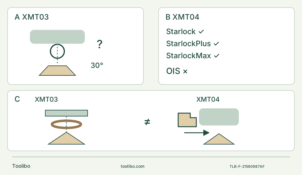
A · Resolve the XMT03 combination
Confirm the exact blade, flange engagement and any correct optional adapter before retaining the system. Thirty-degree positioning is not cross-interface approval.
B · Apply the XMT04 table
Starlock, StarlockPlus and StarlockMax are permitted interface types; OIS is excluded. Still verify purpose and geometry, and use the removable holder bolt and lever correctly.
C · Rebuild the sanding system by model
XMT03 uses its nozzle-band and felt-ring arrangement; XMT04 uses its matching sliding latch attachment and pad. Keep complete assemblies separate and assess suitable dust control.
Original schematic. A asks for exact adapter evidence; it does not approve an unidentified ring or specify pin count. B states interface tiers, not every blade material or task. C compares sanding assemblies only and does not authorize cross-model parts or saw-blade extraction.
Decide what can move to the other tool—and what cannot
An XMT03 owner considering an XMT04 needs more than a claim that both are Makita 18 V oscillating tools. The useful decision is whether a specific blade, sanding system and operating routine can support the next job on the proposed body. This comparison produces a written keep, replace or hold list before purchase or assembly. It is not a speed contest, a current-price recommendation or a claim that one tool is safer in every situation.
The scope is US XMT03 with manual 885329-940 / XMT03-1, and US XMT04 with 885866-944 / XMT04-1 / 20201215. Match the actual body and supplied instructions. XMT04ZB product naming does not establish equivalence with a regional DTM52, and the dated manuals do not prove present kit contents or stock availability. Keep each body’s instructions with its own accessories instead of creating a mixed “Makita multitool” box.
Begin with a single defined task. For example, a short cut through clean, uncoated loose softwood needs an identified wood blade, a supported visible path and enough actual blade reach. Sanding a small bare-wood sample instead needs the correct pad, paper and dust arrangement. Unknown coatings, concealed fasteners, installed hidden services or unsupported stock put either tool on hold. The interface decision cannot make an unsuitable job safe.
Route one: preserve a known XMT03 blade system
For XMT03, the manual describes a flange whose protrusions engage the holes in the application tool. With the battery removed, the lock lever opens fully and the holder bolt comes out. Seat the correctly oriented accessory on the flange, insert the holder bolt all the way to its stop, then return the lever to its original position. The attachment may be set in 30-degree increments; that angular choice does not approve a different attachment pattern.
The manual allows a correct optional adapter for application tools with another installation section. It does not provide a blanket list of every compatible brand, Starlock tier or modern universal-fit claim. If an existing blade depends on an adapter, record the actual blade identity, adapter identity and manufacturer evidence for that exact combination. An unidentified ring in a used kit is not sufficient evidence. Ask Makita for the correct part and permitted accessory combination if those details are missing.
A workable decision can therefore be to retain a serviceable, documented XMT03 system for its already approved wood blade. It can also be to hold that system until an adapter or damaged holder is resolved. Neither outcome requires assuming that the same blade will transfer to XMT04. Do not grind a hole, stack washers, borrow a holder bolt or run the motor to find out whether a questionable combination holds.
Route two: build the XMT04 system from its explicit interface table
XMT04’s US manual positively lists Starlock, StarlockPlus and StarlockMax and explicitly excludes OIS. This is a useful procurement boundary: an identified OIS-only blade is not a carry-over item for XMT04 merely because it was used on XMT03. Conversely, a listed Starlock tier still needs the appropriate cutting material, shape, reach and condition for the task. A tier approval is not approval to cut every material with every blade.
XMT04 also uses a removable holder bolt and lock lever. It is not made into a push-on-only clamp by its Starlock compatibility. With the battery removed, fully open the lever until it clicks, remove the holder bolt, place the accessory correctly on the flange, insert the bolt to its stop and return the lever to its original position. Check secure retention. Keep fingers away from the lever’s closing area; never start either model with its lever open. Do not mount an accessory upside down.
For a new StarlockMax wood attachment that has independent approval for the intended task, XMT04 has an explicit interface path. The cited XMT03 manual does not establish the same tier path, so do not transfer that approval backward. If the desired blade lacks clear material or model evidence, pause the purchase instead of treating XMT04’s longer tier list as a universal solution.
Worked cut decision: the drawer contains an old blade and a new attachment
Suppose the owner has a serviceable XMT03, an identified blade with its exact approved XMT03 mounting arrangement, and a proposed StarlockMax attachment for a short softwood cut. First list which combination is actually documented. The old system may remain a valid choice for that old blade; the new attachment may justify selecting XMT04 only if its purpose and geometry suit the cut. If the old blade is OIS-only, mark it do not transfer to XMT04. If its interface is unknown, mark it hold, not “probably reusable.”
Then check what the choice costs in completed components: correct holder parts, blade, approved power system and any task-specific extraction—not an advertised bare-body price alone. This is a completeness comparison, not a price estimate. If the existing XMT03 already supplies the complete suitable system, the manuals provide no basis for claiming that buying XMT04 will produce a better finish or shorter cut time. If XMT04 is selected for its documented interface, acquire its own matched components and follow its owner procedure rather than adapting the XMT03 stack.
Before any powered sample, use the exact owner’s full safety instructions, required eye/hearing/respiratory protection, secure clamping and both-hand control with vents clear. Both manuals recommend cutting settings 4–6, but their frequency ranges differ: XMT03 is 6,000–20,000 and XMT04 10,000–20,000 oscillations per minute. Identical dial numbers are not evidence of identical frequency, cutting rate or finish. Neither dial should be forced directly between 1 and 6; pass through the intermediate numbers.
Keep the cut aligned and use appropriate pressure, not sideways force against an edge that does not cut. Both manuals require switching OFF and waiting for the blade to stop before withdrawing it from the workpiece. After the controlled sample, remove the battery before inspecting the result. Accept the chosen system only if the intended line, size and breakthrough are achieved without uncontrolled tear-out, scorch or movement of stock/support. A poor result calls for isolated diagnosis and correction, not a performance ranking from one uncontrolled trial.
Worked sanding decision: the pad is not the whole extraction system
Switch OFF, wait for complete stop and remove the battery before installing or removing either sanding/extraction assembly.
For XMT03, the optional dust arrangement includes the nozzle band, dust nozzle, dust attachment, felt ring, pad and holder bolt. The band’s protrusions engage the tool’s holes. The felt ring and pad go on the dust attachment and are secured with the installation bolt. A missing felt ring is a missing specified component, not permission to replace it with an arbitrary washer.
XMT04’s arrangement is different. Remove the holder bolt and accessory, align the dust attachment’s latches with the body notches, slide it into place, then fit the sanding pad and holder bolt and connect the vacuum hose. For removal, take off the bolt and pad, open the latches and slide off the attachment. Do not add the XMT03 felt-ring stack to this procedure or force the XMT03 band onto the other body.
For either tool, use the correct hook-and-loop pad and paper, align extraction holes and choose dust control suitable for the material. These illustrated assemblies are sanding arrangements, not evidence of saw-blade dust capture. XMT04 explicitly prohibits using its extraction attachment when sanding metal because hot particles and sparks can cause ignition. Neither manual allows transferring metal-used sanding paper to wood.
The decision for a small clean-wood sanding task is therefore to obtain a complete model-specific extraction assembly, not merely move the triangular paper. Keep the systems in separate labelled sets. Test an appropriate speed on a clamped sample, use sound paper and complete a surface with consistent grit rather than changing midway. Switch OFF, wait for stop and remove the battery before judging uniformity, unwanted rounding, gouging, burning or shifted stock. Missing extraction components or uncertain dust suitability mean hold the sanding job, even if a saw blade is already qualified.
Control habits must change with the body
XMT03’s indication lamp blinks for low remaining battery capacity and lights for about ten seconds when depletion stops operation. Its documented overload and overheating responses are not the same signal language as XMT04’s front lamp. Do not read the XMT04 lamp using the XMT03 low-charge rule.
XMT04’s front lamp stays lit with the switch ON and goes out ten seconds after OFF. It can blink for about a minute when overheating protection or protection lock operates. Its overload alert may slow oscillation and increase vibration; this is a reason to unload safely, not push harder. Respect the stop-before-withdrawal rule when clearing the cut. An overload shutdown calls for OFF and removal of the cause; overheating needs cooling; depletion needs the approved charging procedure. Repeated protection can lock the tool, for which the manual specifies removing the battery and completing a charge. Do not apply that charging response to every blink or use repeated restarts as a diagnostic test.
XMT04 also documents accidental-restart prevention: insertion with the switch at I does not start the tool until O then I. That does not excuse inserting either body’s battery with the switch ON, nor establish the same function on XMT03. Both require OFF before insertion and full battery engagement with the red indicator no longer visible.
Close the choice with three separate approvals
Record accessory approval, complete task assembly and power/control readiness separately. Both bodies are 18 V, but use only each exact manual’s approved genuine power system and the actual battery/charger instructions. Do not turn a shared platform label into an unverified cross-list charging recipe. This comparison assumes an already commissioned owner system; unresolved pairing is a stop condition.
Choose the documented XMT03 system when it already satisfies the defined job, choose a complete XMT04 system when its explicit attachment route is needed and supported, or hold both until missing evidence or parts are resolved. Keep the chosen model’s full owner guide beside the job. Damaged holders, suspect packs, incomplete lever travel and persistent faults go to qualified Makita service—not to improvised adapters or powered fit tests. The result is a defensible selection and a verified sample, not a declaration that all older accessories transfer or that the newer body always wins.
Models referenced