
Three owner gates: interface, clamp and withdrawal
Three panels show XMT04 18 V interface approvals with battery removed, a three-stage removable-bolt assembly, and O followed by a full stop before straight withdrawal with side force prohibited.
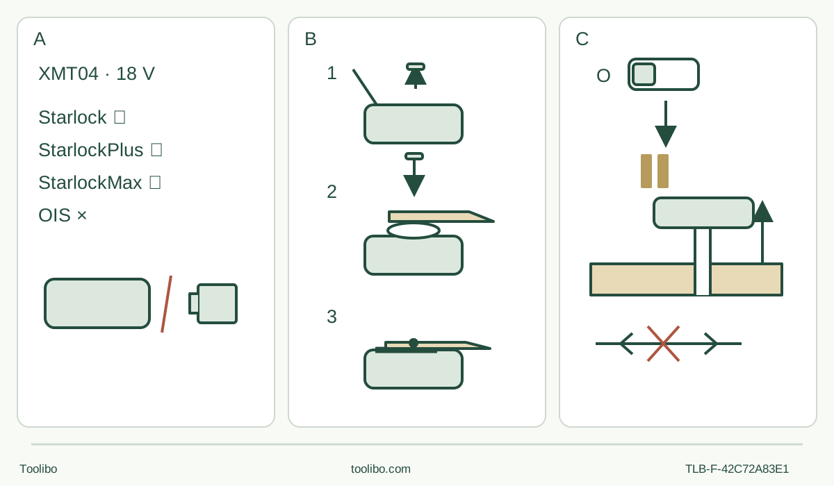
A · Confirm the US interface and isolate
Starlock, StarlockPlus and StarlockMax are allowed; OIS is not. Switch OFF and remove the approved pack before any assembly.
B · Finish the bolt sequence
Open the lever fully to its click and remove the holder bolt. Correctly seat the accessory, insert the bolt to its stop, return the lever and check secure hold.
C · Stop before withdrawal
Switch to O and wait for the blade to stop completely while it remains supported in the cut. Then withdraw without sideways force; remove the battery before inspection.
Original schematic. B uses an uncounted flange and simplified lever, not a dimensional parts drawing; the holder bolt is fully inserted before final lever closure. C requires a complete stop, not merely a brief pause, and does not authorize sideways prying.
Use the US XMT04 identity, not a presumed regional alias
This owner workflow applies to the US XMT04, reached through the official XMT04ZB product page and the linked manual 885866-944, XMT04-1, dated 20201215. Match the actual body and supplied instructions before continuing. It does not establish that the UK DTM52 is the same assembly or that its batteries and accessories transfer unchanged. It is documentation-based guidance, not a hands-on test or a claim about current kit contents.
The outcome is a short, supported cut from the edge of a known, untreated softwood sample. Use an intact Makita-recommended cutting accessory explicitly suitable for that material and this body. The interface table permits Starlock, StarlockPlus and StarlockMax but prohibits OIS. Acceptance of an interface class is not permission to use any material, any accessory length or an unapproved adapter.
Start with a qualified existing power system
The body is rated 18 V DC. Its manual lists BL1815N, BL1820B, BL1830, BL1830B, BL1840B, BL1850B and BL1860B batteries, and DC18RC, DC18RD, DC18RE, DC18SD, DC18SE, DC18SF and DC18SH chargers. Use only a genuine, intact listed pack with its actual manufacturer-approved listed charger, local supply match and full owner instructions already confirmed. This list does not provide a charging sequence, indicator interpretation or promise of regional availability.
The tool’s battery advice specifies charging at room temperature 10–40°C and letting a hot pack cool first; obey any narrower actual charging instructions. Do not store or use the tool and pack where temperature may reach 50°C. Keep contacts clear of dust and loose metal, protect against moisture and do not open, alter or use damaged batteries. An unexpectedly drastic loss of runtime is a stop-and-assess condition, not an invitation to run the pack until empty.
Before inserting or removing the pack, set the switch to O. Hold both tool and pack securely. Align tongue and groove and slide fully until the latch clicks and the red indicator is no longer visible. If it does not slide easily, correct the alignment rather than forcing it. For removal, slide the pack out while operating its front release button. Every adjustment, accessory change and inspection below requires the pack physically removed.
Build the cut around support and clearance
Check the sample’s two faces and full cut path for foreign objects. Do not use an installed wall, trim with unknown fixings, chemically treated timber or unidentified coatings for this first project. Mark a short line starting at an accessible edge. Clamp the retained stock to a stable bench and support the offcut so it cannot pinch the blade or fall dangerously. Clear the entire blade approach and below-work travel of bench surfaces, clamps, hands and cords.
Wear safety goggles complying with ANSI Z87.1, proper hearing protection and a respirator suitable for the dust; keep the area ventilated and bystanders clear. Hold the tool firmly by its intended insulated grip, with hands and face away from the accessory. Do not use the battery as a pushing surface. Keep footing secure and ventilation openings clear. No liquid coolant or wet workpiece is allowed. If the chosen position cannot preserve control, support and full visibility, change the setup rather than proceeding.
Fully insert the holder bolt before returning the lever
With the switch OFF and battery removed, allow hot parts to cool. Open the lock lever fully until it clicks and remains open. Remove the holder bolt. Hold the tool securely and keep fingers away from the lever’s original resting position: it can close suddenly and pinch them.
Place the correctly oriented approved accessory on the tool flange. Do not install it upside down. Orient it for the task using the permitted 30° positions, then insert the holder bolt all the way until it stops. Return the lever to its original position and check that the accessory is securely held. This is not the Milwaukee threaded-bolt hand-tightening method and not a Bosch press-to-snap installation. Never start the XMT04 with its lever open.
If the accessory does not seat or the bolt cannot reach its stop, do not force the lever, substitute hardware or test it under power. Remove the pack, identify the mismatch and obtain the right accessory or authorized service. To remove an accessory, follow the assembly sequence in reverse while isolated and after it has cooled.
Set the dial without forcing it across the ends
The XMT04 operates at 10,000–20,000 oscillations per minute, moving 1.8° to each side, 3.6° overall. The numbered dial runs from 1 to 6; higher numbers raise the rate. Move through intermediate numbers when changing direction. It cannot wrap directly from 1 to 6 or 6 to 1, and forcing it can damage the tool.
The manual recommends 4–6 before cutting. Select within that range only as appropriate to the actual blade and sample, respecting any accessory restriction. Sanding has its own trial-setting instruction, not an automatic transfer of the cutting recommendation. Soft start reduces the starting reaction and constant-speed control helps maintain the selected rate, but neither permits excessive force or an unsupported workpiece.
Cut, stop in the work, then withdraw
Recheck accessory security, the closed lever, clamps and clearance. Insert the approved pack with the switch at O. Start with the accessory clear of the work by sliding to I. Bring the cutting edge to the marked line and advance with an appropriate light load so the cutting motion does not slow under force.
Do not drive the tool sideways in a direction where the accessory has no cutting edge. In particular, do not bend a long blade by pressing harder. Maintain support through breakthrough; keep hands away from moving parts and never reach under the work. If control, clamping or cutting action becomes uncertain, stop instead of trying to complete the cut at any cost.
For ordinary withdrawal and completion, the XMT04 safety instruction is explicit: switch OFF and wait for the blade to stop completely before removing it from the workpiece. Keep it supported while stopping, then withdraw without levering it sideways. Wait for a complete stop before setting the tool down. Remove the battery before clearing waste or checking the result, and allow the blade and sample to cool.
Accept the cut only if it follows the intended line and size, achieves the intended complete separation, and shows no uncontrolled tear-out, scorching or support movement. No dimensional tolerance is invented. If it fails, correct the accessory choice, support or pressure on another sample before working on valuable material.
Respond to the actual protection state
Excessive pressure can trigger an overload alert: the oscillation slows and vibration amplitude increases. The manual tells the operator to take the accessory out of load and resume with an appropriate load. For this cutting project, reconcile that with the stopped-before-withdrawal rule: switch OFF, wait for a full stop, withdraw, assess the setup and reduce pressure before a deliberate restart. Do not treat increased vibration as a reason to push harder.
Actual overload shutdown is separate: switch OFF and stop the application causing high current before restarting. Overheat shutdown requires cooling the tool/battery before reuse. Insufficient charge requires removing and charging the pack under its actual approved instructions. Do not confuse these conditions with the anti-restart function, which prevents starting after battery insertion with the switch at I; deliberate O then I is its reset, but normal insertion must still be at O.
Repeated protection operation can produce a protection lock that does not clear merely by toggling OFF and ON. The manual’s specified release is to remove the pack and complete charging on the approved charger. This is not a universal cure for damaged parts, a hot pack or a recurring fault; respect the actual charging safety limits and obtain service if normal operation cannot be restored safely. Do not keep provoking the lock or bypass protection.
The front lamp stays on during I operation and normally goes out ten seconds after O. It blinks for about one minute during overheat protection or protection lock, so that blink alone does not distinguish the two. Packs equipped with an indicator have their own check-button display and possible protection indication; use the actual pack table rather than treating a light as proof of battery health or authenticity.
Keep optional sanding and maintenance within their limits
A later sanding task needs the proper pad and an intact abrasive with holes aligned to the pad. Do not use worn or gritless paper, and never reuse paper that sanded metal to sand wood. Select a sanding rate by a separate trial; maintain the same grit across the whole surface before moving to another grit.
The optional sanding dust attachment has a specific assembly: battery out, holder bolt and accessory removed, attachment latches aligned with the tool notches, then slide the attachment into position as illustrated. Refit the sanding pad and fully inserted holder bolt, close the lever, and connect the suitable vacuum hose. To remove it, take off bolt and pad first, open the latches and slide the attachment off. Do not copy the XMT03 felt-ring arrangement. Do not use this extraction attachment for metal sanding: collected sparks and hot particles can cause smoke and ignition. It is not a demonstrated saw-blade dust hood.
Clean the tool while isolated. The manual calls for cleaning and lubricating the lock lever’s moving part from time to time so dust does not impede movement, but specifies no lubricant chemistry or quantity; obtain Makita guidance rather than spraying an arbitrary solvent into the mechanism. Never use gasoline, benzine, thinner or alcohol for cleaning. Repairs and other adjustments belong with authorized Makita service using Makita parts. Store with the battery removed, terminals protected and the exact manual retained for the next inspection.
Models referenced