
Seat, adjust through the numbers and distinguish sanding extraction
Three panels show abstract flange/accessory engagement and holder-bolt insertion, the full 1–6 dial sequence without an endpoint shortcut, and dust attachment above felt ring and sanding pad.
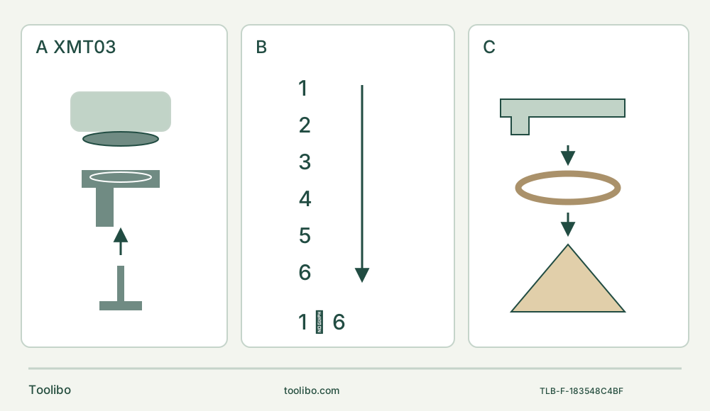
A · Complete the holder sequence
With the battery out, open the lever fully, remove the bolt and seat flange protrusions in the actual accessory holes. Insert the bolt to the stop, return the lever and check retention.
B · Respect the dial stops
Move through intermediate numbers between 1 and 6, never force directly across an endpoint. Cutting is recommended at 4–6 within the actual accessory limits.
C · Do not omit the felt ring
For the separate complete optional sanding system, secure the nozzle band and fit dust attachment, felt ring and pad in the specified order, then retain with the holder bolt and connect the appropriate hose.
Freshly checked schematic with uncounted engagement outlines: these are not a pin count or actual hole shape. A requires the battery removed and the complete lever procedure. C is a partial view of the optional sanding stack; the nozzle band, matching holes and holder-bolt retention remain required, and it is not a saw-blade hood.
Match the US XMT03 before borrowing any procedure
This first project is a short controlled cut in a loose, known, unfinished softwood sample using an existing US Makita XMT03. The current XMT03Z product page links the XMT03 instruction manual marked 885329-940 and XMT03-1. Match the actual label, controls and owner-supplied instructions. The file’s creation metadata is not a printed revision date, and this article does not claim that another regional model or XMT04 has the same mounting procedure.
The distinctive sequence is a fully opened lock lever, a removable holder bolt inserted to its stop, and then the lever returned to its original position. It is not the threaded hand-tightening sequence of a Milwaukee tool and not a snap-in Starlock clamp. This is a documentation-based owner guide, not a hands-on test or a promise about today’s included adapters.
Choose a sample whose two faces and full cut route are visible. Exclude installed walls, floors, unknown coatings, hidden services and embedded metal. The manual expressly says to inspect for and avoid nails. A short open bench task is a sensible way to learn the exact holder and stop procedure without pretending that a shallow cut makes an unknown structure safe.
Use a previously qualified genuine power pair
The tool is 18 V DC. The matched manual lists BL1830, BL1840, BL1815 and BL1815N battery cartridges and recommends BL1830 or BL1840 for continuous operation. The current product describes genuine 18 V LXT Star-marked packs. For this bounded workflow, use an intact genuine battery approved by the actual matching owner instructions and a compatible Makita charger already commissioned under its own instructions. Do not infer every newer pack or a third-party adapter from the voltage alone.
This article does not provide a new charger setup or charging tutorial. Read the actual battery and charger instructions and confirm their physical labels. The tool manual’s battery-care guidance includes charging at room temperature 10–40°C and letting a hot pack cool, but that does not replace a charger’s specific requirements or establish its input supply. If the power system is not already qualified, do not proceed to a powered cut.
Inspect the tool, switch, holder, blade and battery. Stop for damage, binding, an unreliable switch or an unexpectedly much shorter battery operating time. Do not open the pack, short its terminals or expose it to water. Do not store the tool or battery where the temperature may reach 50°C or more.
Always switch OFF before fitting or removing a cartridge. Support both tool and pack, slide the button at the pack’s front and slide the pack out. Remove it before all adjustments, functional checks and accessory work. For reinsertion later, align the tongue and housing groove, slide fully until it clicks and verify the red indicator above the button is hidden. A visible red indicator means it is not fully locked. Never force a cartridge that does not slide easily.
Seat the protrusions, insert the bolt to the stop, then close
Use an identified Makita-recommended accessory intended for this model and the actual material. For the short sample cut, choose an approved sharp wood-cutting blade with enough usable reach for the thickness and clear movement below the work. Do not fit an accessory upside down. The available 30° positions are for choosing an appropriate working angle, not permission for an orientation that places the cutting edge against a hand or the tool.
With OFF selected and the battery removed:
- Open the lock lever fully and remove the holder bolt.
- Clean the mating surfaces and inspect them. Place the accessory on the flange so that the flange protrusions engage the accessory holes correctly.
- Insert the holder bolt all the way to its stop.
- Return the lock lever to its original position, keeping fingers clear because it may close suddenly and pinch.
- Check that the accessory is seated and held securely while still isolated. Never start with the lever open.
The bolt’s insertion-to-stop step is essential. Do not substitute an invented torque value, a few turns of a different fastener or a “close the lever and hope” method. Remove the accessory by reversing the installation sequence after the tool has stopped, the battery is out and the blade has cooled. Sharp edges remain hazardous even when cold.
The manual allows a correct optional adapter for an accessory with a different installation section. That requires the exact compatible assembly, not an improvised washer or universal fit assumption. Current product information names different adapter references in separate places; this guide does not decide what is in an owner’s kit from that inconsistent listing. If your accessory needs an adapter, positively identify the actual approved adapter and its instructions first, or choose an approved direct-fit accessory. Do not modify the holder or accessory.
Arrange support, clearance and dust controls
Mark the cut on the visible sample and inspect the whole thickness. Clamp it to a stable platform; never hold it against your body or in a free hand. Arrange retained-piece and waste support so the kerf will not close on the blade and the waste cannot fall unpredictably. Leave the full blade movement clear of clamps, supports and bench. Keep hands out from underneath the cut.
Use suitable safety glasses or goggles rather than ordinary spectacles, hearing protection, and the correct dust mask or respirator for the material and operation. Provide ventilation, keep bystanders clear and use suitable dust collection where provided and connectable. Unknown paint or treated material needs a different assessment; it is not part of this clean-wood sample. The optional sanding extraction assembly described below does not establish saw-blade dust capture.
Keep the work dry. The tool is not waterproof, and neither water on the surface nor a liquid-cooled accessory is permitted. Hold the insulated gripping surfaces firmly, keep your face and hands clear of the accessory and plan access to the switch without losing control. Do not operate the tool while carrying it or leave it running unattended.
Set the dial through its intermediate numbers
The overall range is 6,000–20,000 oscillations per minute, with 1.6° movement to each side, 3.2° total. The dial runs from 1 to 6, with higher numbers increasing frequency. It cannot turn directly across the end stop from 1 to 6 or from 6 to 1. Move through the intermediate numbers; forcing an endpoint damages the mechanism.
For cutting, the manual recommends presetting 4–6. Select within the actual blade and material limits and test on the secured sample. It does not give a calibrated OPM value for every dial mark, and this is not a 1–12 Milwaukee or five-level FLEX control. Complete setting changes with the tool OFF and battery removed, as required for adjustment.
Confirm the lever is closed, accessory secure, blade clear of the material and switch at O before inserting the qualified pack. Slide the switch to I to run. The tool-specific safety instruction requires the accessory to be clear of the work at startup. Then engage the sample with controlled forward feed, without loading it enough to slow the cutting motion.
Cut, then stop before withdrawing the blade
Use the cutting edge in its intended direction. Do not force the tool sideways in a direction where the accessory has no cutting edge. Excess pressure reduces efficiency and can lock the motor. Watch the work support, blade position and kerf through the whole short cut rather than staring only at the marked line.
The manual recommends clearing sawdust by drawing the tool appropriately, but its safety rule requires switching OFF and waiting for the blade to stop before removing it from the workpiece. Combine those instructions: pause, stop completely, withdraw safely and clear the cut with the system isolated when handling near the accessory. Do not pull out a running or bound blade merely to clear chips.
If the work shifts or the tool stalls, set O, wait for stop and remove the pack before correcting the setup. Finish the last part without tearing away the waste or pinching the blade. Set OFF and wait for complete stop before withdrawing the blade from the work or setting the machine down. Remove the battery before examining the finished edge. The blade and work may be hot; allow them to cool and inspect for splinters without sliding a hand along the cut.
With the battery removed and the sample cool, compare the cut with the intended line and size and confirm that the planned through-cut is complete. Accept the sample only if it was completed without uncontrolled tear-out, scorching or shifted support. If the cut missed the intended result or those defects occurred, reject that trial and correct the support, accessory, setting or feed before the next sample. No numerical dimensional or surface tolerance is implied.
Distinguish low charge, overload and heat
A blinking indication lamp means remaining capacity is low. At much lower capacity, the tool stops and the lamp lights for about ten seconds. Set OFF, remove the pack and use the already qualified charging process. This signal is not a numeric battery-percentage gauge or a worklight-afterglow rule from another model.
For an overload, the manual calls for moving the switch to O and stopping the action causing the overload before deliberately restarting. If an overheated battery prevents starting, let it cool. If the tool itself overheats and stops, let the tool cool before restarting. Isolate the system before physical inspection or freeing an accessory. Never keep cycling the switch, bypass protection or borrow a maximum-speed no-load cooling routine from another manufacturer’s tool. An electronic stop is not battery removal and does not establish a blanket no-restart guarantee.
Return to work only after the cause has been corrected and the normal setup checks repeated. Damage, repeated unexplained stops, abnormal noise or a failed switch require Makita service rather than another trial.
Keep the optional sanding system separate
If a later task requires sanding, first inspect the approved pad for cracks and fit suitable paper in the correct direction, with its extraction holes aligned to the pad. Do not use worn paper or paper without grit, and do not reuse paper previously used on metal for wood. Test the setting on scrap and use the same grit over the whole workpiece for that pass rather than changing grit midway across one area.
The matched manual illustrates a complete optional dust assembly. With the battery removed, install the dust nozzle and dust attachment, then secure the nozzle band with its protrusions engaged in the tool’s holes. Fit the felt ring and sanding pad on the dust attachment and secure them with the holder bolt using the normal full-insertion/lever procedure. Connect an appropriate vacuum hose to the attachment. The felt ring is not an optional spacer to omit, and the nozzle-band engagement is not replaced by the pad bolt. Missing or mismatched parts mean the sanding system is not ready. This does not authorize the same stack around a saw blade.
Inspect and store without internal repairs
Switch OFF and remove the battery before maintenance. Clean accumulated dust from the lock lever’s moving part; the manual calls for periodic lubrication there but does not identify a lubricant in this document. Obtain the appropriate Makita guidance rather than inventing a spray or applying oil indiscriminately to the holder.
Do not use gasoline, benzine, thinner, alcohol or similar cleaners. Brush inspection and replacement, repairs and other service adjustments belong to Makita authorized or factory service centers using Makita parts. Store the clean dry tool with battery removed, accessory edges protected and terminals clear of metal objects. The old manual’s warranty paragraph is not current warranty advice. This project ends with a finished visible cut and a checked, isolated owner system.
Models referenced