
Isolation, wrench clamp and stop-before-withdrawal
Three schematic panels show a separated battery and OFF tool, an uncounted engaged flange with hex-wrench bolt tightening, and cutting dial 3–5 followed by OFF and full stop before withdrawal.
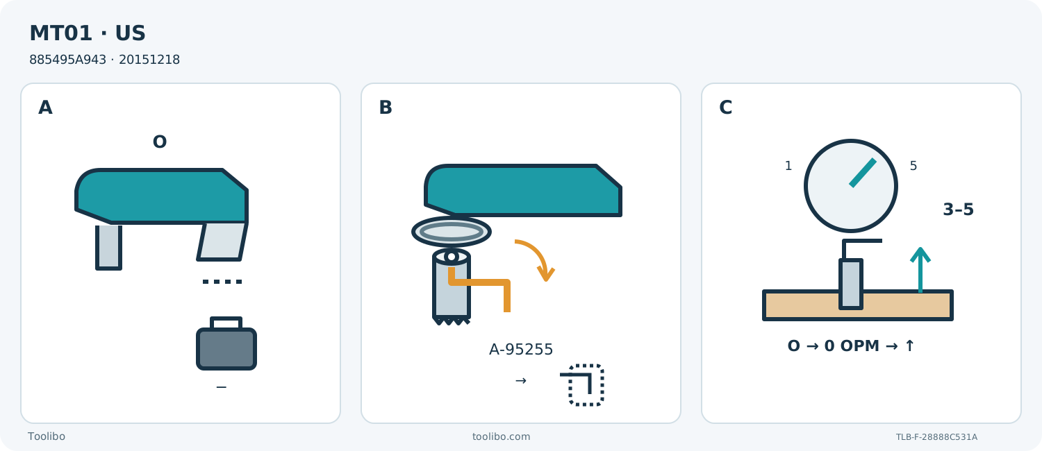
A · Isolate the exact body
Match the US MT01 and its instructions; select OFF and remove the battery. A later insertion requires the approved pack fully clicked in with the red indicator hidden.
B · Engage, tighten, remove the wrench
Seat the original blade on the flange protrusions and firmly tighten the installation bolt with the hex wrench. No lever or extra washer is inferred; remove and store the wrench before power.
C · Cut, stop, then withdraw
Use cutting preset 3–5 through intermediate dial positions. Start clear, advance lightly, select OFF and wait for complete blade stop before withdrawal; remove the battery before acceptance.
Original schematic, not a pin count, dimensional drawing or torque specification. A is battery-out isolation, not standby. B requires actual flange engagement and firm bolt tightening before the wrench is removed and stored. C uses the cutting recommendation, not exact per-setting OPM; wait for complete stop before withdrawing.
Match the discontinued US body and its instructions
This project is for an existing US Makita MT01 that matches manual 885495A943, MT01-1, printed 20151218. The current official MT01R1 page marks that configuration discontinued and still links this manual and the historical product flyer. MT01R1 and MT01Z are package identities for this body, not two tools counted separately. No current stock, supplied-kit revision or warranty promise follows from the old documents.
The distinguishing installation is a threaded accessory bolt tightened with a hex wrench. Do not use the XMT03 lever/holder-bolt sequence or XMT04 Starlock procedure. The supported job here is a small visible cut in known loose softwood using an actual identified original A-95255 plunge blade. The historical MT01 flyer lists that blade, and the official 2016 accessory catalog page 123 identifies it for plunging in soft and hard wood. This does not authorize a replacement model, every bi-metal blade or hidden installed work.
Close the power prerequisite before assembly
The matched tool is rated 10.8 V DC/12 V Max CXT; its table lists genuine BL1016, BL1021B and BL1041B batteries. The historical MT01R1 flyer identifies BL1021B and DC10WD as its original battery/charger combination. Use only an actual already commissioned genuine approved system with its own battery and charger instructions available. This guide does not teach charging, equate every “12 V” pack, or promise those parts are in a present kit. If the actual power-system identity or instructions are missing, pause.
Switch OFF before inserting or removing a battery. Hold the tool and pack securely. Slide the button on the front of the pack and slide the pack out for removal. To insert later, align its tongue with the housing groove and slide fully until it locks with a click. The red indicator above the button must no longer be visible; visible red means incomplete locking. Do not force a pack that does not slide easily.
Keep batteries away from water, conductive objects and heat, and never use a damaged or altered one. Stop immediately if operating time becomes excessively short. Do not open the pack or probe its contacts. The tool manual’s storage warning excludes places reaching or exceeding 50°C; actual component instructions may impose additional limits. A cool-looking pack is not proof of a safe charging condition.
Plan a fully visible loose-wood cut
Choose new uncoated softwood whose full cut region, both faces and underside can be inspected. Remove uncertainty about nails, screws or other foreign material before proceeding. Do not infer that a bi-metal label allows cutting hidden nails: this tool’s specific safety instructions say to avoid nails and inspect/remove them before operation.
Mark a short open-edge cut only after comparing the actual blade’s usable reach with the stock and checking the whole moving envelope. There is no sample thickness or manufacturer capacity invented here. Clamp the retained stock to a stable platform and support the waste so it cannot drop, pinch the blade or require a hand near the teeth. Keep the bench, clamps and all body parts clear, including below the work.
Wear proper safety glasses or goggles—not ordinary spectacles—hearing protection and the appropriate dust mask/respirator for the material. Apply suitable dust controls and ventilation. Keep loose clothing, hair and gloves away from moving parts; use protective gloves for sharp or hot accessory handling. Do not use water or liquid coolant on this tool or workpiece. If the task cannot be made fully visible and controlled, choose another method.
Seat the original blade and tighten the actual bolt
With the switch OFF and battery removed, inspect the blade, flange, bolt and hex wrench. Do not install an upside-down, cracked, distorted, blunt or unidentified accessory. The manual permits accessory orientations at 30-degree intervals, but the chosen angle must still leave a controlled grip and a clear blade path.
Place the blade on the tool flange so the flange protrusions engage its holes completely. Secure it by tightening the actual application-tool installation bolt firmly with the hex wrench. The instruction is firm tightening, not a supplied numerical torque. No extra washer, arbitrary screw or lever action is part of this native assembly. Inspect seating and retention while isolated; do not run the motor to settle a doubtful mount.
Remove the hex wrench from the bolt and store it in the tool’s illustrated holder. For removal, remain OFF with the battery out, allow a hot blade to cool, loosen and remove the installation bolt with the hex wrench, then take off the accessory. The optional adapter shown in the manual is for particular different installation sections; it is not blanket approval for a competitor’s accessory. This original-blade project does not use an inferred adapter recipe.
Source basis: MT01 manual page 7, Figures 6–10; historical MT01 flyer NTF-0615 and 2016 Makita catalog page 123. The accessory catalog’s descriptions are not a claim of current availability.
Set the dial without crossing its stop
The dial runs from 1 to 5, with higher numbers giving higher oscillation frequency. It must pass through intermediate numbers; do not force it directly from 1 to 5 or from 5 to 1 across the stop. The tool’s overall range is 6,000–20,000 oscillations per minute, but the manual does not give an exact OPM conversion for every dial mark.
For cutting, page 8 recommends a preset of 3–5. Select within that range for the actual blade and sample rather than borrowing another Makita’s 4–6 scale. Set and check the function with OFF selected and the battery removed. Once all setup checks are complete and the wrench is stored, verify OFF again and install the qualified pack fully.
Slide toward I to start. Do not look directly into the light. The front lamp illuminates with ON; it is not an independent light-only stage. To stop, press the rear of the slide as described in the lamp section and slide toward O/OFF. Do not borrow another model’s trigger, lock-on button or staged lamp control from a marketing picture.
Cut lightly, then stop before withdrawing
Hold the tool firmly in its intended grip areas, with a stable stance and hands and face away from the blade. Start with the accessory clear of the work. Bring the blade to the marked cut and advance so its motion is not slowed by excessive load. Do not push the tool sideways where the accessory has no cutting edge, bend the blade or lever the last fibers. Do not operate by pressing the battery against the tool or using the pack as a support.
Stop for binding, shifting stock, abnormal heat or an insecure attachment. The exact safety instruction is important: switch OFF and wait for the blade to come to a complete stop before removing it from the workpiece. Do not import a moving-blade withdrawal instruction from another brand. After withdrawal, remove the battery before inspecting, clearing material, repositioning stock or changing the blade. Wait for complete stop before setting the tool down, and avoid unnecessary no-load running.
Inspect the isolated sample against the intended line and size. Accept it only if the cut has fully separated and there is no uncontrolled tear-out, scorching or evidence that the support moved. A failure means correct a documented setup problem or seek qualified assistance before another sample. No structural-fit tolerance or hands-on performance claim is supplied.
Keep battery indication separate from protection
Only battery models ending in B have the illustrated check-button capacity indicator. Its bands are approximate and can vary with conditions; they do not measure pack health or certify runtime. Do not confuse that pack display with the tool’s front lamp.
For overload, the manual directs switching OFF and stopping the application that caused it before a deliberate restart. If it will not restart because the pack is overheated, allow cooling. The front lamp can blink when overload and tool/pack temperature reach the protection threshold; remove the cause and cool both tool and pack. Low battery voltage may allow a brief restart followed by another stop: remove the pack and use its actual approved charging instructions, rather than repeatedly trying to finish the cut. Isolate before any physical correction, never bypass protection, and obtain service for damage or recurring unexplained behavior.
A separate sanding setup is not automatically ready
Before installing or removing any sanding or extraction assembly, select OFF, wait for complete stop and remove the battery. The manual’s sanding route needs the correct pad and sheet with matching shape and extraction holes, securely fastened by the actual installation bolt. Do not use worn paper, paper without grit, or a sheet used on metal to sand wood. A wood cutting setup does not establish a ready sanding or extraction system.
For the optional extraction attachment, the documented order is joint, dust nozzle and dust attachment; then engage the nozzle band’s protrusions in the tool holes; then place the felt ring and sanding pad on the attachment and secure with the installation bolt. Connect a suitable vacuum only after the actual equipment and material requirements are established. The manual specifically prohibits using this extraction attachment when sanding metal because sparks and hot particles can cause ignition. It is not a saw-blade capture claim.
Leave the system isolated and serviceable
After the job, select OFF, wait for stop and remove the battery. Keep the actual blade identity, bolt, wrench and instructions together. Do not clean with gasoline, benzine, thinner, alcohol or similar agents. Inspection and care remain battery-out; repairs and other maintenance or adjustments belong to Makita authorized or factory service using Makita replacement parts.
The completed outcome is an accepted known-wood sample and a correctly stopped, isolated tool—or a documented parts/power/service hold. It is not proof that an old kit, a replacement blade or an unverified battery can be used interchangeably.
Models referenced