
Separate the battery, then complete both locks
A shows OFF and a separated generic battery with a document check, not a named power pairing. B separates the lever’s counterclockwise unlock cue from the rod’s clockwise removal cue. C separates neutral uncounted accessory seating, rod press/counterclockwise securing and clockwise lever return. D is a plan-view full cut corridor with retained clamp and independent waste support.
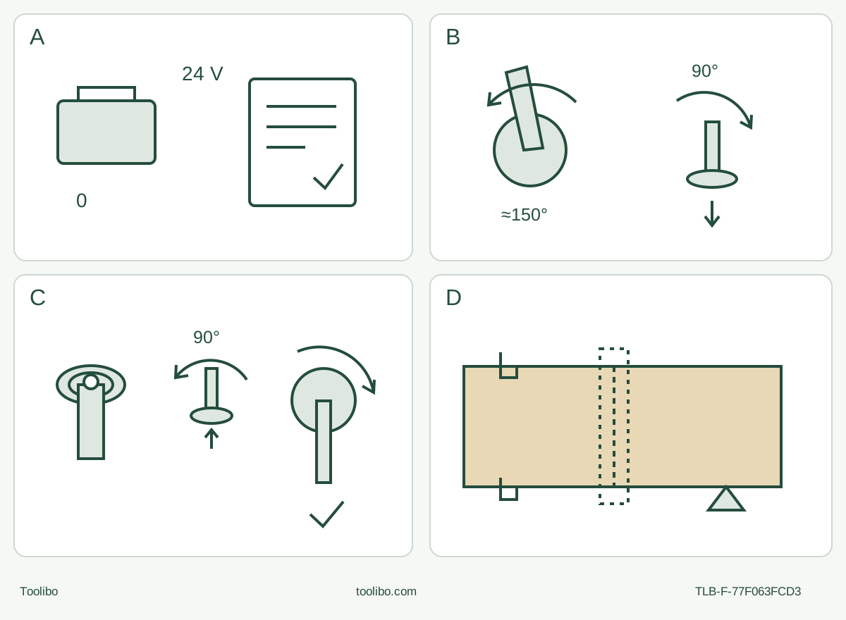
A · Establish isolated eligibility
OFF and complete stop, then actual release buttons and forward pack removal. The diagram keeps the pack separate; its own approved instructions establish power eligibility.
B · Open lever and remove rod
With battery out, lever counterclockwise about 150 degrees to unlock, rod 90 degrees clockwise out, then remove the cooled old accessory. Keep the rod from facing the ground and fingers out of pinch zones.
C · Seat, secure rod and return lever
Align all grooves/protrusions; align rod rib, press and turn 90 degrees counterclockwise. Turn lever clockwise through locking click and fully home. Check isolated original seating.
D · Complete a supported cut
Use original H, preselect medium–high while stopped, maintain actual barrel grip and clear free hand. Keep support outside the whole path; OFF/full stop before withdrawal and battery-out acceptance.
Original schematic, not scale. Turn directions are read from the actual source views; the isolated sequence in the text controls. A does not show a charging or battery-removal direction. C’s lever must pass the locking click and continue to its original position; no pin count or torque is supplied. D requires real underside clearance and actual barrel/free-hand control.
A complete owner project starts before the battery goes in
Use this guide only with the actual US Kobalt KMT 124B-03 and its matching AB16408 instructions. The current own-brand Lowe’s product links that manual; its cover identifies items 0790024/0790023. Those are not extra tool models, and this is not a guide to KMT 224 or a promise about a currently supplied kit. The manual specifies a 24 V DC body and 11,000–20,000 OPM. Do not turn a product family name into permission to attach an unidentified battery.
This is an existing-system project. Record the actual manufacturer-designated Kobalt battery and charger identities and have their own matching complete instructions available. They must already be commissioned for this body. The tool manual does not provide a named pack/charger list from which this article can establish a new pair; a broad “all 24 V” product statement is not a substitute. An uncertain, damaged or modified power component stops the project. This guide neither charges a battery nor supplies a temperature, indicator or disposal recipe for one.
The cutting accessory is the positively identified original plunge-cut blade H, named “wood & metal” in the manual’s inventory. Here it is used only on known clean loose softwood. Establish that the actual original blade is recommended for this body, suited to the material and rated for the actual tool, with intact mounting features and enough usable reach. An unmarked look-alike is not identified by silhouette alone. No blade part number, width, cut depth or replacement-kit inclusion is invented. Do not substitute the circular blade I or import its separate applications into this project.
Evidence: KMT 124B-03 AB16408 cover and pages 2–3, 7 and 11; exact own-brand product and its selected Use and Care Manual.
Set a visible, supported task and its dust boundary
Mark a short straight cut that fully separates a piece of known dry, new, untreated, uncoated softwood. Inspect both faces and the whole route for screws, nails, grit and other foreign material. The stock must be loose and independently accessible—not installed flooring, a wall or a hidden cavity. Actual reach, body clearance and support determine whether this sample is possible; there is no universal thickness allowance.
Clamp the retained piece to a stable bench. Independently support the offcut so it can separate without falling uncontrolled, tearing out the last fibres or closing the kerf. Keep every support and clamp outside the full blade movement and breakthrough space. Check the approach, underside, actual barrel grip, free hand and any hose route while the tool is isolated. Do not hold stock or catch waste with the free hand. If safe support and an inspectable exit cannot coexist, change the task or stop.
Prepare a dry, well-lit workplace with secure footing and bystanders clear. Exclude flammable liquids, gases and explosive dust atmospheres. Use ANSI Z87.1 eye protection with side shields and a full-face shield when needed, appropriate hearing protection and protective gloves during cutting as well as accessory changes. Keep clothing, gloves and hair away from moving components. The manual calls for ventilation, suitable approved masks that filter microscopic particles, protective clothing and avoidance of prolonged skin contact with dust.
For harmful, combustible or explosive dust, the manual requires a dust mask and dust/chip extraction when connectable; an explosive atmosphere is not made acceptable by wearing a mask. The current product specifies no dust extraction, so do not invent a native port, clip-on hood or a nearby-hose capture guarantee. Establish the actual task/environment dust-control arrangements and their equipment instructions. If a suitable required control cannot be established, the project is on hold, however small the sample. Isolate both tool and extractor before any equipment connection or adjustment, then operate/check the qualified equipment under its own instructions before cutting.
Evidence: AB16408 pages 4–7; product dust-extraction specification. The loose-stock support and acceptance plan is a bounded project design, not an OEM capacity claim.
Isolate and inspect the original mechanism
Move the slide switch toward the rear to OFF and wait for complete standstill. Press the actual battery-release buttons and pull the pack forward off the tool, following Figure 1b. OFF is not battery isolation. Protect the separated pack from metal objects under its own instructions; do not open it or improvise terminal repairs.
Check the housing, barrel grip, switch, lever, original locking rod and drive shaft, accessible hardware and the blade. Missing or damaged parts, cracks, unreliable controls or abnormal prior vibration mean no battery insertion until qualified correction. Use only a sharp, undamaged blade: a bent, blunt or otherwise damaged one may break. Allow an old cutting accessory to cool and wear gloves before handling its sharp edges.
Keep the tool supported while changing accessories. Do not point the locking rod toward the ground during removal: the source warns that the accessory can fall off unexpectedly. The mounting procedure has two separate locking actions, and the first click is not the end of installation.
Complete the rod turn and the lever’s return
With the battery removed:
- Turn the head’s clamping lever counterclockwise about 150 degrees until the unlocking click. Keep fingers out of the gap between the lever and tool body.
- Turn the original locking rod 90 degrees clockwise and pull it out. Remove the old accessory before fitting a replacement. Keep fingers out of the rod/drive-shaft gap and retain the original parts.
- Ensure the locking rod and drive shaft are clean. Place the original blade H on the shaft with all its grooves aligned to the corresponding protrusions. For this straight sample, choose a forward-facing position. Do not mount it backward toward the body.
- Insert the rod with its rib aligned with the tool body. Press it and rotate it 90 degrees counterclockwise so it is secured in the drive shaft.
- Turn the clamping lever clockwise. After the locking click, continue until the lever returns to its original position. Hold it firmly without entering the pinch zone. Check the completed original assembly while still isolated; unresolved seating or retention is a stop condition, not a powered test.
The manual permits 30-degree orientation increments, but that does not approve a backward blade, universal interfaces or another manufacturer’s locking rod. Do not add washers, use a hex bolt instead or infer torque from the stated rotation angles.
Evidence: AB16408 pages 10–11, actual Figures 5a–5c and 6a.
Select speed while stopped, then make the cut
The dial has positions 1, lowest, through 6, highest. Never change speed while the tool is running. For the original H plunge-cut route the manual specifies medium to high speed for the initial cut, without an exact numbered setting. Select that range while stopped and isolated, and qualify the setup on a supported scrap of the same known material. Do not map “medium” to an invented number or turn the dial under load. If a later change is needed, stop fully, remove the battery and re-establish the setup first. The possible later speed increase on page 11 does not cancel page 9’s stopped-only warning.
Before insertion, reconfirm OFF, the complete rod/lever lock, original blade direction, cleared tools, stable support and actual dust controls. Align the pack’s raised rib with the tool groove, slide the qualified pack on and confirm its latches snap securely. A pack that does not seat correctly is not forced into place.
Hold the actual main barrel grip as shown in Figure 6b, keeping vents clear and the free hand outside the work and blade envelope. No auxiliary handle is assumed. Maintain control with the blade clear of the wood, push the slide switch forward to ON, and establish the selected operating speed before contacting the marked route. Do not force the plunge. The original H instructions describe keeping its teeth in the work while moving the back of the tool slowly sideways to assist the cut. This is controlled relief in the selected straight cut, not permission to twist a trapped blade, steer a curve or widen an unsupported kerf.
If the stock shifts, the blade binds, the attachment moves or sound/vibration becomes abnormal, stop rather than reproduce the fault. Move the switch rearward to OFF and maintain control until complete standstill. The manual expressly requires the tool to stop completely before removal from the workpiece. Withdraw along the clear path, set it down securely and remove the battery before inspection or any correction.
Keep the three states separate
The head LED illuminates when the tool is switched on and turns off after OFF; it is not an isolation or standstill indicator. Rapid flashing means the tool stopped to protect its internal circuits. The source requires OFF and cooling before a later restart; this is not a prompt for repeated trials, a battery repair or bypassing a fault. Slow flashing means very low battery charge, a separate condition governed by the actual power-system instructions. Neither light state explains loose hardware or authorizes continuing an abnormal cut.
A repeatable unexplained stop, damaged component or insecure accessory requires qualified help. Any documented isolated correction must be complete before the whole setup is reassessed. There is no powered diagnostic procedure here.
Accept both faces and leave the system isolated
Let the blade and work cool, keeping clear of teeth and splinters. Check that the intended line and size are achieved, the cut is fully through, and neither face shows uncontrolled tear-out, scorching or shifted support. A hidden bridge, unacceptable edge or evidence of movement means this sample is not accepted. Correct an established setup problem before another sample, or seek qualified advice; do not claim a numerical tolerance that the source never gives.
With the battery removed, clean only with a soft dry cloth and keep the tool’s ventilation slots clear. The manual says never use detergent or alcohol, and reserves maintenance for a qualified technician. Store the tool, protected sharp accessory and power items safely under their own instructions. The finished outcome is an inspectable cut and a known isolated system—not a generalized authorization for the other accessories pictured in the inventory.
Evidence: AB16408 pages 8–11 and 15–16. No current kit, runtime, repair-cost or warranty promise is made.
Models referenced