
Four checks for the qualified Nuron owner
Four panels show owner/document qualification, battery-isolated lever and blade placement, six speed stages retained after a 15-second display timeout, and separate short-press status versus longer-than-three-second health checks.
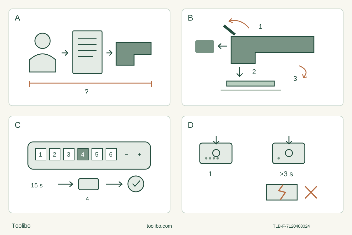
A · Close the qualification gate
A trained authorized owner needs the exact body instructions and an already approved, commissioned Nuron B 22 battery/charger system. Missing pairing evidence means stop and ask Hilti.
B · Isolate, seat, then lock
Remove the battery. Turn counterclockwise fully past the detent: jaws closed. Lower the aligned body onto the insert, then turn clockwise under control to the stop: jaws open and lock.
C · Read and deliberately select the stored stage
Six stages use plus/minus buttons. The OFF display expires after 15 seconds without erasing the setting; change stage only OFF or unloaded, never during a loaded cut.
D · Separate charge status from health
A short press requests charge/fault information; holding longer than three seconds requests health. Check re-engagement after pressing an installed pack and reject misuse-damaged batteries regardless of a green result.
Original schematic. A is an unresolved qualification question until training and actual power documents match. B is a sequence, not a measured battery-removal direction or internal jaw drawing. C highlights 4 only to illustrate memory, not a recommended starting stage. D distinguishes signal requests; no indication certifies an undamaged battery.
A qualified owner, not just a compatible-looking battery
This is a documented bench-cut workflow for the Australian SMT 6-22, generation 01, matched to Hilti instructions 2381015, Pos. 1, dated 20240813. The manual restricts operation, servicing and maintenance to trained, authorized personnel who know the hazards. Reading this article does not supply that training. The outcome is one controlled cut in clean, uncoated loose softwood, followed by an isolated acceptance decision—not a blind installed repair.
The tool operates at 21.6 V with Hilti Nuron B 22-series lithium-ion batteries. Before starting, the owner must already have an actual approved battery and charger, their complete matching instructions and a commissioned charging system. The downloaded tool manual refers to an end-of-document battery/charger table, but its printed pages 520–522 are blank. Consequently this article does not name a charger pairing or teach charging. A battery’s physical fit, a promotional photograph or a voltage label cannot close that missing qualification. Ask Hilti for the exact system evidence if it is not already available; stop here until it is.
Check the body, switch, grips, battery housing and contacts for damage or contamination. Do not use a dropped, pierced, damaged, modified or repaired battery, and do not try to make a rejected pack work. A battery that is too hot to touch requires the manual’s fire-safe handling and Hilti assistance, not another test cycle. With the switch back at OFF, remove the battery before any mounting, gauge adjustment, cleaning or close inspection.
Select a blade and a genuinely visible sample
The StarlockMax holder accepts StarlockMax, StarlockPlus and Starlock accessories, but the interface name alone is not a complete approval. Use an intended, recommended accessory whose permitted oscillation frequency is at least the tool’s maximum 20,000 oscillations per minute. Reject bent, dull, cracked or otherwise damaged inserts. Never orient an insert back toward the grip.
Hilti’s W4586 0523 0-en 1 selector lists the wood HCS Starlock blade, 50 × 32 mm, as single article 2368500 or ten-pack 2381639. Its softwood cell is a solid recommendation; hatched cells for hardwood, laminate and chipboard mean possible use, not the same recommendation. Use the positively identified wood blade and clean softwood for this exercise, not a similar-looking metal blade or an unidentified mixed-material sample. The dimensions identify the accessory, not a guaranteed cut depth.
Inspect both faces and the entire intended blade path. Exclude nails, screws, coatings, hidden services and unknown contamination. Clamp the retained piece to a stable bench, support the waste against dropping or closing the kerf, and leave the full oscillating blade envelope clear of bench, clamps and hands. Do not hold the stock in one hand. Choose a short accessible edge-start cut with a visible marked line and a thickness within the actual blade’s usable reach. If breakthrough and the far side cannot be observed or supported, change the sample rather than reach blindly underneath.
Assess wood dust and arrange suitable extraction and respiratory protection for that material and workplace. Wear the manual’s eye, hearing and head protection; handle sharp or hot inserts with protective gloves. Keep both hands on the tool, maintain a stable stance and leave the vents clear. This is dry work: no water cooling, wet scraping or solvent treatment. No work at height, tether arrangement, grout or chemical-removal procedure is included.
The two-click mounting sequence has counterintuitive jaw states
With the battery removed, clean the mating surfaces of the insert and holder. Put the blade on a flat surface. Turn the clamping lever counterclockwise completely past the first detent to its stop. In this change position the holder jaws are closed. Align the tool’s star-shaped mount with the blade and lower the tool onto it.
Hold the lever and turn it clockwise, under control, fully past the detent to its stop. The jaws open to secure the insert. Do not let the lever snap back. Check that the blade is securely engaged before inserting any battery. If the lever will not complete its travel or the accessory does not seat correctly, stop and resolve identity, cleanliness or damage with the power removed; do not force or modify either part.
For removal after work, switch OFF, wait for complete stop and remove the battery. Allow for heat and sharp edges. Hold the tool and insert just above a surface so the released insert cannot fall far. Turn the lever two clicks counterclockwise to release, then close it clockwise. This is not a threaded flange that is tightened with a wrench, nor a reason to infer compatibility with every oscillating-tool blade.
Separate collar adjustment from the cutting route
The supplied securing collar and gauges are not permission to cut into unseen construction. If checking their setup, keep the battery removed. Use the hex on the depth gauge or parallel guide to loosen the collar’s clamping screw. Align all four positioning lugs with the notches in the neck, slide the collar on, choose its angle and tighten that screw. The separate positioning screw secures the inserted gauge or guide; it does not replace the collar clamp.
For the depth gauge, distance X runs between the insert tip and gauge tip. If the insert is angled, loosen the collar clamp, turn the collar until the gauge is parallel with the insert and retighten. Set X with the positioning screw and ensure the gauge cannot touch the insert anywhere in its full oscillation. A depth setting neither locates utilities nor proves clearance beyond the work.
The parallel guide’s cutting mode is a different operation: Hilti requires the insert to remain fully plunged throughout the entire oscillating stroke. A corner emerging above or below the work can cause kickback. Do not transfer that guide procedure to an ordinary partly engaged edge cut. For this sample, remove the optional collar/gauge arrangement while isolated and use the clearly supported, unguided edge-start route. A guide-equipped cutting project needs its own exact geometry assessment and the full manual procedure.
Remembered speed is not a safe-start indication
With setup complete, verify OFF and clean, unobstructed battery contacts. Insert the qualified battery until it clicks, then check secure seating. The six speed stages use plus/minus buttons and an LED display. With the tool OFF, a button press shows the stored stage; select deliberately rather than assume the last user’s setting is suitable. After 15 seconds the display goes out, but the chosen stage remains in memory. A dark speed display does not mean the battery is isolated or the setting was erased.
The cutting instructions start at a medium stage for initial plunge control and allow a higher stage after entry. They do not supply a numbered universal medium setting; the figure’s highlighted 4 is only a memory illustration. Most importantly, change speed only with the tool OFF or running unloaded, never while the blade is under load. For this bench exercise, make any change with the switch OFF and the blade fully stopped and clear.
Take the working position with the insert clear of the wood, hold with both hands and slide the switch forward to start. Approach the marked edge under control and use moderate pressure, keeping the blade aligned. Do not force progress or twist the insert to steer. Severe vibration during entry means excessive pressure, not a request for more force. If the stock shifts, the insert binds or control deteriorates, switch OFF, wait for complete stop, remove the battery and correct the setup before another attempt. Do not conduct a powered fault test.
Complete the short cut without reaching into the waste path. Slide the switch back to OFF, wait for all movement to stop before laying down or closely inspecting, and remove the battery. Accept the sample only if the cut follows the intended line and size, breaks through as intended and shows no uncontrolled tear-out, scorching or evidence that the stock or support moved. There is no invented numerical tolerance: reject an unsuitable result, identify its cause while isolated and correct the next sample’s setup.
Read the right battery signal, without treating it as certification
A short press of the battery release button requests charge/fault status. If pressed while the battery is installed, subsequently confirm it is re-engaged and secure. Four steady green LEDs mean 100–71%, three 70–51%, two 50–26%, one 25–10%, and one slowly flashing green means below 10%. A quickly flashing green LED means discharged; use the already qualified charging procedure, and contact Hilti Service if it repeats after charging.
Quick yellow flashing can mean overload, excessive heat or cold, or another fault. Stop, restore the documented working conditions and avoid overload; persistent indication needs Hilti Service. Steady yellow means an incompatible tool/battery combination, and quick red flashing means a locked battery: consult Hilti Service, not an improvised reset or alternate charger.
Holding the release button for longer than three seconds requests a different health check. After the sequence, steady green allows continued use; quick yellow means the check did not complete, so repeat as instructed or seek service. Steady red means remaining capacity below 50% if a connected tool still operates; if it no longer operates, the battery has reached end of life and needs replacement/service. This is not a reason to run a damaged battery to see what happens. The manual explicitly says this check cannot detect some misuse damage, including dropping, piercing or external heat. No LED result proves authenticity, undamaged condition or future runtime.
Leave a clean, isolated system
With the battery removed, clean vents gently with a dry soft brush and the housing with a slightly damp cloth; do not use silicone-containing cleaners. Clean the product contacts with a dry, clean cloth. Do not touch the battery contacts or remove their factory-applied grease. Do not open the tool or repair a battery. Damaged parts, persistent faults or incomplete clamping require Hilti Service.
Transport and store with the battery removed, contacts protected and no loose unprotected packs. Keep the system dry, away from direct sun and heat sources, and observe the actual tool, battery and charger instructions rather than transfer a tool temperature limit to charging. The completed outcome is a checked sample and a safely isolated, documented owner system—not a general approval for every material, insert or power combination.
Models referenced