
Isolation, lever sequence, blade speed and clear breakthrough
A shows O and an upward battery-removal cue. B shows a raised forward lever and a neutral uncounted engagement outline, then a separate downward locking cue. C links MMD32PBC to about dial 4, not an exact intermediate oscillation rate. D shows retained wood clamped and waste independently supported with a blade extending into free space.
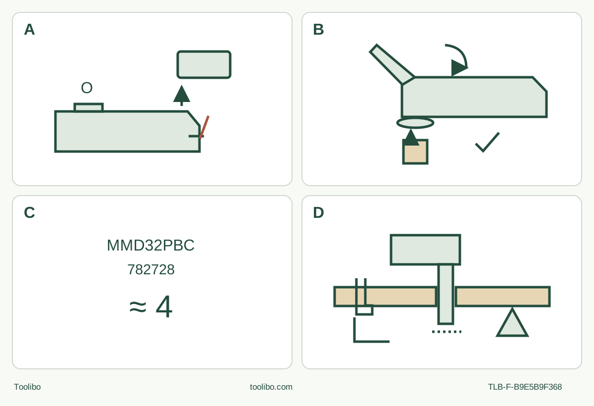
A · OFF and pack out
Slide to O, wait for full stop, press latches and lift the battery fully upward before any setup.
B · Raise, seat, lower
Remove the cooled old accessory, seat the original blade evenly and lower the lever to lock; keep fingers clear and check without power.
C · Use the blade-specific setting
MMD32PBC: about two-thirds maximum, about dial 4. Do not turn the full machine range into a universal wood recipe.
D · Complete and inspect
Clamp retained stock and independently support waste. Stop fully and remove the pack before accepting the cut or correcting the setup.
Original conceptual schematic. A follows actual latch release and upward removal, not a charger instruction. B is not an exploded holder or pin-count drawing. C is specific to the named blade in the matched manual. D does not specify a safe depth or hand location; actual reach, complete sweep, grip and support must be checked.
First match the UK owner system
This project is a short, fully visible cut through new uncoated loose wood, not an opening in an installed wall or trim. It is for the UK CV18DMAW2Z owner whose actual CV18DMA body, type C366012S and supplied instructions match C99752681 G / 412. The current UK manufacturer’s Documentation route leads to that exact European manual. It does not establish an Australian variant or make every similarly named kit interchangeable.
The selected original blade is MMD32PBC, part 782728. The manual names it, and the manufacturer’s Belgian Edition 8 accessory table identifies that same part for wood and metal. Here it is used only on clean wood. That table supplies same-part material evidence, not UK stock, included-kit contents or an approved cutting depth. Its stated blade length is not a capacity rating. The UK product’s generic blade listing does not prove which blade an owner actually has. If the marking, original identity, condition or permitted application is uncertain, stop and obtain the exact accessory information.
The useful result is more than a mounted blade: a complete cut on the intended line, with no unexplained movement or damage, followed by an isolated inspection. The owner must be able to see the full route and provide adequate blade reach and clearance before starting.
Qualify power without inventing a charging routine
Use only an already commissioned original BSL1820M 18 V, 2 Ah battery and UC18YFSL charging system whose actual labels and supplied instructions have been checked. The matched manual identifies this pair; it is not a current W2Z kit promise or permission to substitute another battery because it slides into the mount.
There is an unresolved charging-temperature discrepancy within the selected document: the additional warning says 0–40°C, while its charger table says 0–50°C. This guide does not choose a new charging limit or teach charging. If the actual power-system instructions and qualified guidance do not resolve safe use, the project remains on hold. Do not copy the manual’s battery-cycling recovery prose into a fault experiment.
Do not use damaged or modified power items, deformed terminals, a battery with unusual heat, smell, leakage or deformation, or a charger/system of uncertain condition. Follow the actual power-item instructions and qualified service guidance for safe disposition; do not dismantle, repair cells or improvise transport. Tool and battery operation is specified at −5–40°C. Storage is below 40°C, dry, protected from conductive debris and inaccessible to children.
Isolate and prepare the complete cutting route
Slide the switch rearward to O, wait for complete standstill and press the battery latches to lift the pack fully upward, as Figure 3 shows. A switch setting, restart-protection feature or dark lamp is not isolation. Keep the battery separate while choosing, changing or inspecting the blade.
Inspect the housing and grip, slide switch, lever, attachment ring and accessible original fasteners. Broken, loose or deformed parts, unreliable controls or an unexplained holder condition require qualified correction before use. Check terminals for swarf without putting conductive objects into them. Do not energize the tool to reproduce a defect.
Choose sound, known dry wood with no nails, screws, coatings or other foreign material. Keep the work area dry; the matched manual prohibits wet applications. Both faces and the exit area must be visible. Clamp the retained portion securely to a stable support; support waste independently so it can separate without closing the cut. Never hold the stock by hand. Check the full accessory sweep and breakthrough route against clamps, support and the surface below. If the actual blade cannot pass through with clear space throughout, change the workholding or choose a different qualified method—not extra pressure.
Arrange suitable wood-dust controls and appropriate respiratory protection for the actual task, with ventilation and the equipment’s own instructions. The native dust adapter described later is not a saw-blade capture system. If the cutting dust cannot be controlled appropriately, do not run the sample. Wear eye and hearing protection, suitable footwear and close-fitting clothing; keep bystanders clear, maintain stable footing and keep the grip dry and clean.
Raise, seat and lower: the actual holder sequence
Let an old blade cool and wear suitable protective gloves for sharp-accessory handling. With the battery removed, raise the lever to its unlocked position. Carefully remove the old application tool before positioning a replacement; do not stack accessories. Keep fingers clear of the spring-loaded lever and attachment area.
Seat the original MMD32PBC squarely on the attachment ring in an orientation that suits the visible route. Figure 6 permits accessory orientation in 30° steps; this is not a lever-turn or fastener-torque instruction. Lower the lever to its locked position. The source warns that its strong spring can trap fingers. Check that the blade is evenly and securely seated without power.
There is no separate sleeve-and-shaft sequence to borrow from an older body, no added washer and no invented screw torque. If the accessory appears loose or uneven, remove the battery if necessary and repeat the documented isolated attachment procedure. An unresolved fit or worn holder is a service hold, not a reason to force the lever or try a powered wobble test.
Inspect the blade before use: reject dull, excessively worn, bent, cracked or otherwise suspect cutting edges and bodies. Its actual marking and working geometry must still agree with the chosen task after installation.
This blade has a specific speed boundary
The machine’s dial spans 1–6 and the manual specifies 6,000–20,000 oscillations per minute. That range alone does not authorize maximum speed for every wood blade. MMD32PBC is explicitly listed for about two-thirds of maximum speed, about dial 4. Preserve that blade-specific instruction rather than converting it into an exact intermediate oscillation rate or a universal wood setting.
Set the selected control while isolated. The manual notes that some frequencies can cause vertical accessory vibration and should be avoided. That is not permission to tune away a damaged blade, loose holder or violent unexplained behavior. Stop, isolate and assess the actual condition; unresolved abnormal operation requires service.
With the workspace ready, confirm O and insert the qualified pack downward until secure. Hold the machine firmly with one hand on the housing grip shown in Figure 2, not on its metal front. Keep the other hand and the body clear of the blade and underside route. Do not transplant another tool’s grip geometry.
Start with the blade clear of the wood by sliding forward to I. Let it run at the selected operating speed before contact, then feed gently on the marked path. Keep firm control without unreasonable force or twisting the blade to steer. The LED blinks when the switch is turned on; do not look directly into it or treat this as a battery-fault code.
If the stock moves, the cut pinches, the blade appears loose or abnormal vibration develops, slide to O, wait for complete stop and remove the battery before examining the setup. Do not clear chips around a moving accessory or repeatedly restart a stopped tool to discover the cause.
Stop, inspect and decide whether the sample passes
After full separation, slide to O and wait for complete standstill before withdrawing on the clear route or setting the tool down. Keep it away from chips and sawdust while it is still moving. Remove the battery and allow hot parts to cool before handling the sample or blade.
Accept the sample only if it follows the intended line and size, has complete breakthrough, and shows no uncontrolled tear-out, scorching, shifted support or unexplained attachment movement. No numeric tolerance is invented here. If the result does not meet the intended use, correct the identified material, support or accessory issue while isolated and plan a new sample. Suspected equipment damage ends the project for qualified service.
Ordinary heat management and fault recovery are different. After continuous cutting or grinding, the manual calls for roughly 15 minutes’ rest when changing the battery; a hot housing also needs a break. Do not turn this into powered cooling of a faulted system. The pack’s display distinguishes static charge bands, a single flashing low indication, all flashing for overheating and the outer pair flashing for malfunction. Keep these indications separate from the switch-on light and follow the actual battery instructions rather than inventing a reset routine.
Sanding extraction is a different qualified setup
Before any sanding or extraction change, establish O, full stop and battery removal. The manual restricts its dust adapter to MSU93D. Its illustrated sequence uses adapter 382793, felt packing 382794, the original MSU93D 782791 pad and aligned sanding paper before lever closure and the hose connection. This does not approve saw-blade capture, a substitute pad or an arbitrary felt ring.
A sanding project would additionally need the complete matching extraction system, suitable wood paper and its actual instructions. Do not reuse paper that has worked metal on wood, or use worn or clogged paper. This cutting project does not claim that separate system is ready.
For care, keep the tool isolated and use a soft dry cloth or one moistened with soapy water on the exterior; avoid chloric solvents, gasoline and paint thinner. Keep the motor dry and refer internal faults to qualified service. Preserve the actual model, document and blade information with the tool for its next setup.
Source basis: CV18DMA C99752681 G / 412, English 5–11 and actual Figures 1–11/specification and accessory pages; current UK product and Documentation/manual-index chain; Belgian Edition 8 accessory table, printed page 27. This is a document-based owner workflow, not a hands-on test, current kit guarantee or Australian equivalence.
Models referenced