
Three relationships in a controlled depth trial
Three panels show a rotated blade and parallel gauge, X between blade tip and bent gauge tip, and a partial-depth sample kerf to inspect after isolation.
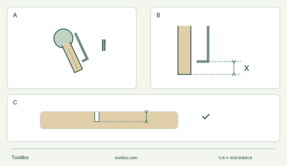
A · Keep the gauge parallel to the blade
With the battery removed, align the collar tabs with neck grooves; rotate the collar to follow the permitted blade orientation and securely tighten its locking bolt.
B · Set the actual tip-to-tip X
Insert and position the exact depth gauge; set X from blade tip to gauge tip, then tighten the separate locking knob. Confirm stable contact and clearance without inventing a torque or tolerance.
C · Accept only the isolated actual result
Make a controlled trial on firmly clamped known loose wood, stop and remove the battery, then check the visible depth, line and unchanged setup. A failed or slipping setup is corrected or held, not transferred to a finished part.
Original schematic, not scale or a rated blade angle/depth. A means rotation around the mounting axis, not a bevel cut. B measures actual tip-to-tip difference, not housing distance. C is the intended partial-depth acceptance check on visible loose stock; its checkmark is not a guarantee from setting X. Both collar bolt and separate guide knob must be secured, and full blade clearance remains necessary.
Make the stop follow the blade, not the housing
Rotating a plunge blade on a FLEX FX4111 changes where its cutting end lies relative to the tool. A depth gauge left at the old collar angle may no longer be parallel to that blade. Tightening only the guide knob does not correct the collar angle, and tightening only the collar bolt does not secure the guide’s sliding position. This project sets both independently and proves the result on visible loose wood before considering a depth-limited cut useful.
Use the exact FX4111 body, its matching attachment collar and depth gauge, and the actual owner’s instructions. The bounded blade is the documented FLEX FA401002 HCS wood/plastic plunge blade, used here only on new uncoated softwood. Confirm that the actual accessory is intact, appropriate and rated at least 20,000 OPM as the manual requires. No third-party collar, homemade stop or broad Starlock compatibility is inferred.
The tool also needs its already commissioned undamaged battery/charger system expressly listed in the matched manual, with those components’ instructions available. This is not a charging tutorial or a current kit-content claim. Missing exact parts or unresolved power identity means hold the project rather than improvise a stop.
Choose a depth that can be independently checked
Use a loose softwood sample large enough to clamp securely. Inspect both faces, its edges and the whole proposed cut area; exclude metal, unknown coating or any hidden contents. Pick a short test kerf at an accessible edge so the cut’s depth can be examined from the side after isolation. Do not place the first trial in the middle of a valuable finished part or over an unseen service.
No numerical depth is prescribed here. The chosen target must be within the actual blade’s usable reach, the actual gauge adjustment and the stock thickness, leaving material below the trial cut. Mark that intended depth on the visible side as a project reference, not a manufacturer tolerance. If the geometry cannot provide a reliable gauge contact surface and a visible acceptance check, change the sample or method.
The “angled” blade in this project means rotated around the tool’s mounting axis for access. It does not mean making a bevel with a tilted tool or bending the blade. Keep the intended plunge orientation and reference surface consistent throughout the trial. The stop is not a detector of wires, pipes or a safe distance to concealed objects.
Mount the blade while isolated
Switch OFF, wait for complete stop and remove the battery before any assembly, adjustment or blade handling. Let hot parts cool and wear protective gloves for the sharp accessory. Inspect the blade, holder, collar, bolt, guide and knob for damage, missing parts or debris that prevents proper seating. Do not run a damaged or incomplete assembly.
For the FX4111 blade change, turn the release lever counterclockwise past the first click and resistance to the second click. The holder jaws are then closed for the change. Place the accessory on a flat surface and align the star interfaces at the desired permitted orientation. Do not face the accessory backward. Return the lever clockwise to its original position; the jaws open and lock the accessory. Check secure engagement before proceeding. These unusual closed-for-change/open-to-lock states must not be reversed.
If removing an old blade, the two-click release lets it fall free. Provide a safe landing area and do not catch a hot or sharp falling accessory. Inability to obtain secure normal engagement is an exact-parts or qualified-service hold, not a powered seating test.
Install the collar and identify its two separate locks
The collar locking bolt secures the collar’s position around the tool neck. The separate locking knob secures the inserted depth gauge. They solve different problems.
Use the hexagonal rod of the depth gauge or guide fence to loosen the collar locking bolt, as the manual specifies. Align all four positioning tabs of the clamp assembly with the neck grooves. Install the collar assembly, adjust its angle and securely tighten the collar locking bolt. Do not force a tab onto a ridge or leave the collar apparently tight but incorrectly seated.
Loosen the separate locking knob to insert the depth gauge, then establish the required position. If the blade is rotated, loosen the collar locking bolt and rotate the collar around the neck until the depth gauge is parallel to the blade; tighten that bolt again. The gauge’s bent tip may be above the blade or to its side as the matched instructions illustrate. Choose only a position that can contact the intended reference surface without colliding with the blade, workholding or stock edges.
Set X as the distance between the plunge-blade tip and the depth-gauge tip. It is not a distance measured from the housing, blade shoulder or clamp. Tighten the guide’s locking knob to retain that setting. Check both the collar bolt and guide knob, parallel alignment and the actual tip-to-tip distance while still isolated. No torque number, scale accuracy or guaranteed cutting tolerance is supplied here.
Source basis: FX4111 instructions, page 11, Figures 8a–9; page 18, Figure 13. This depth-gauge procedure is separate from the straightedge/edge-guide procedure on page 19; no edge-guide feed direction is transferred into this task.
Check the whole approach before restoring power
Clamp the sample to a stable platform with the visible test edge accessible. Support it so it cannot rock or shift under gauge contact. Keep the entire blade motion, the collar, bent gauge tip and housing clear of clamps and the bench. The gauge must meet a solid, stable reference surface rather than a narrow waste edge that may break away. Even though the target is shallow, leave the full area below and beyond the blade clear; do not use the stop as the only protection for the bench or a hand.
With the battery still removed, check the approach without forcing the teeth into the wood. Confirm that the chosen blade orientation permits a secure two-hand cutting grip, keeps vents clear and leaves the switch accessible. If the gauge would contact a clamp first, slide off an edge, bridge an uneven surface or prevent proper tool control, stop and redesign the setup. Do not solve a collision by moving the gauge aside while leaving the old X assumption unchanged.
Provide eye and hearing protection, suitable respiratory protection and dust controls for the material. Wear the protective gloves required by the tool instructions. Remove adjustment items, confirm the slide is rearward OFF and securely install only the qualified battery. Check the speed panel while OFF: initial plunge uses level 3. Its remembered previous setting and dark-panel timeout do not guarantee that level.
Make one controlled trial, then measure the result
Hold the tool securely with both hands, blade clear of the stock, and start. Approach the marked line with light pressure, letting the blade cut rather than forcing it. Keep the gauge aligned with the intended reference surface. After initial entry, any change of speed must be made only OFF or in the manual’s controlled no-load condition, not with the blade engaged. For this short depth trial there is no need to increase speed merely to finish sooner.
When the gauge reaches its intended contact, stop advancing. Do not press harder to compress the stock, bend the stop or seek extra depth. Unexpected vibration, a moving collar, shifting stock or unreliable contact means stop immediately and isolate before checking. Switch OFF, wait for complete stop and remove the battery before touching the kerf, adjusting either lock or removing the sample.
Examine the visible side and cut with the tool isolated. Compare actual depth with the intended project mark using an appropriate measurement method. Accept the trial only if the intended limit and line were achieved without unintended breakthrough, scorching, torn stock, shifted support or changed collar/gauge position. The schematic check is an inspection decision, not a promise that setting X guarantees the result.
If the trial is too deep, uneven or outside the intended result, do not reuse that setting on a finished workpiece. Identify and correct only a documented setup error while isolated, then use a fresh suitable sample. A slipping lock, damaged guide, incompatible component or repeat unexplained error needs exact replacement information or qualified service. Do not add adhesive, washers or excessive tightening force to compensate.
Record the blade identity and orientation, reference surface, intended X and isolated acceptance result. After changing a blade, its angle or the reference geometry, repeat the alignment and trial rather than inheriting the previous depth claim. The finished outcome is a verified bounded sample setup—or a clear decision not to use that configuration—not authorization to plunge into an unseen wall.
Models referenced