
Opposite disk routes and a complete dust connection
Four panels show exact TE-MG 300 EQ 4465150 and 21021 with a disconnected cord, closed-ring mounting without disk 14, open-slot mounting with the disk convex toward the inverted tool below, and aligned extraction adapter followed by anticlockwise locking.
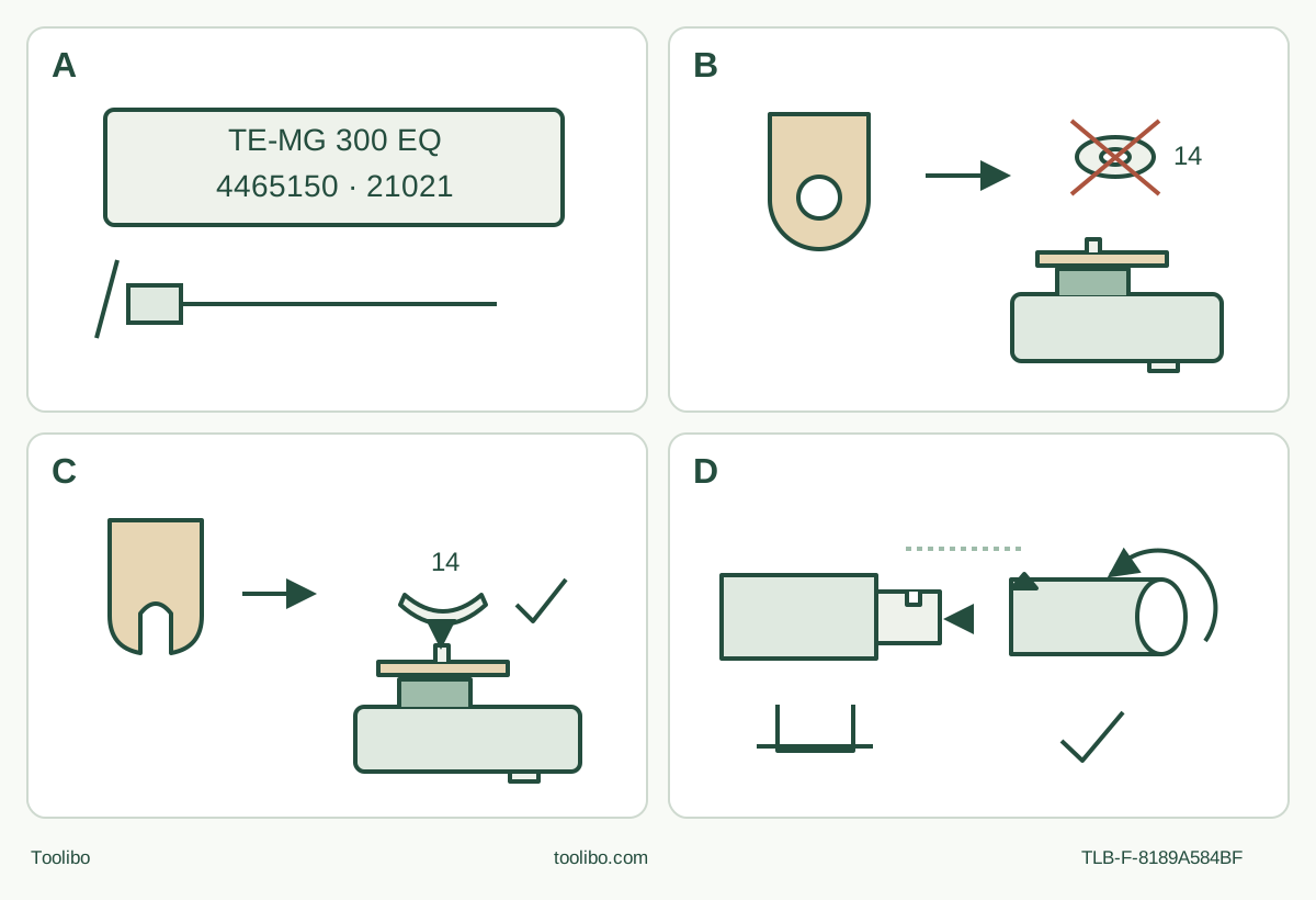
A · Identify and unplug
Match article 4465150 and I.-Nr. 21021, move the switch OFF and disconnect mains power before setup.
B · Closed ring: no disk
Use the documented closed-ring route without disk 14; keep all chuck pins engaged while closing the quick-release lock.
C · Open slot: disk required
For the approved illustrated open-slot accessory, use disk 14 with its camber toward the tool, then lock and check security.
D · Connect extraction completely
Use the intended fastening clip, align adapter arrow A with recess B and turn anticlockwise until engaged; qualify the whole extractor and hose system.
Recovered original schematic checked against the freshly read manual and disk supplement. The cross-section clarifies direction; it does not claim universal fit or a locating-pin count.
The disk is conditional, not a spare part to add everywhere
On the TE-MG 300 EQ, two accessory shapes require opposite treatment of disk 14. The manufacturer’s illustration shows a closed-ring accessory installed without the disk, but an open-ended, slotted accessory installed with it. For the latter, the disk’s camber faces the tool. Adding the disk to every accessory is not an extra safety precaution; omitting it from the illustrated open-slot arrangement is not a harmless shortcut.
This owner guide follows article 4465150, I.-Nr. 21021, the linked May 2021 operating manual, its separate one-page disk supplement and the linked May 2025 safety booklet. Confirm those identifiers against the actual machine and supplied instructions. The current French manufacturer page supplies the document bridge, not permission to combine another identification number, a similar battery model or a differently named kit. We do not infer tool weight from conflicting product summaries or promise present stock.
The completed task is a short, controlled cut in known, untreated, removed softwood using the identified original wood plunge blade, followed by checking the result and storing the corded system. The mounting distinction is useful even when a later approved accessory has another opening, but that does not establish universal accessory compatibility.
Isolate the corded tool and identify all needed parts
Move the slide switch backward to OFF, then unplug by holding the plug, not pulling the cable. Unplug before every adjustment, accessory change, extraction change or cleaning operation. OFF alone is not isolation. Keep the disconnected plug under your control while preparing the tool.
Check the housing, cable, plug, switch, quick-release mechanism and accessory seating surfaces for damage or looseness. A switch that cannot reliably turn the machine on and off, a damaged lead or a distorted accessory means stop and obtain qualified service. Do not open the motor or attempt a mains-cable repair. Compare the actual supply with the nameplate; this matched manual specifies 230–240 V AC, 50 Hz and 300 W. Do not substitute another voltage or regard a travel plug as an electrical conversion.
Locate the original quick-release parts, disk 14, wood blade 9, and the complete extraction assembly: front device 6a, fastening clip 6b and adapter 3. The manual’s component numbers are identifiers, not a claim that every second-hand sale contains those pieces. If the correct retention part or dust connection is missing, obtain the exact replacement before using the affected setup. A magnet holding the accessory temporarily is not a substitute for mechanical clamping.
Choose the correct mounting route while unplugged
Open the quick-release lock as shown in the manual. Hold the machine with its ON/OFF switch pointing down and the chuck facing upward, in a stable position. This is the assembly orientation, not a cutting posture. Clean the engagement surfaces without reaching across sharp teeth; allow a used accessory to cool and use protective gloves when handling it.
For the documented closed-ring blade, place the accessory on the chuck so the chuck pins enter the accessory recesses. The magnet helps keep it in place during clamping. Follow the crossed-out disk illustration: do not add disk 14 to this closed-ring route. Close the quick-release lock while making sure the pins remain engaged, then check the accessory is firmly held.
For an actually compatible open-ended accessory of the illustrated type, follow the separate supplement and manual figures: use disk 14 with its camber facing the tool, then complete the same correct pin engagement and closed lock. In the inverted assembly view, “toward the tool” means toward the machine beneath the accessory, not automatically upward on the page. Do not substitute a flat hardware-store washer or decide compatibility solely because an opening slides over the holder. If the accessory, disk orientation or seating cannot be confirmed from the matched instructions, stop at that gate.
The recommended first sample uses the identified original wood blade rather than experimenting with an unverified third-party mount. The chuck’s adjustable positions do not remove the requirement for full engagement, clear working space and a secure final check. Do not invent a bolt torque for a quick-release mechanism.
Complete the dust route before energizing
The safety booklet requires available extraction and collection equipment to be connected and used correctly. Treat the entire connection as part of readiness, not as an optional accessory photograph. With the plug still out, open the quick-release lock and stabilize the tool as described for mounting. Place extraction device 6a onto the chuck area in the illustrated orientation, then latch clip 6b into the specified air-vent locations. Use those intended locations; do not improvise a clamp across other cooling openings.
Fit adapter 3 so its arrow A aligns with recess B on device 6a, and turn the adapter anticlockwise until it engages. The text’s cross-reference for this adapter is misleading: the actual connection is shown in figure 6. Use the arrow/recess geometry and named parts, not the wrong figure number. Connect a suitable extraction unit and hose, confirm the joint is secure and route the hose without pulling the tool or fouling the cut. Reconfirm accessory retention after arranging the front assembly.
A fitted plastic tube is not proof of adequate dust collection. The extractor must be suitable for the material and used under its own instructions. If that complete system is unavailable or the connection obstructs this accessory, resolve it before proceeding rather than running a knowingly incomplete setup. Do not convert the manufacturer’s general description into a numerical collection-efficiency or exposure guarantee. Ventilation and suitable respiratory protection remain necessary.
Make the whole sample accessible
Inspect both faces of the removed wood and the full intended blade path for foreign objects and fasteners. This exercise excludes unknown coatings, wet materials, asbestos and concealed building services. Clamp the sample so it cannot slip, support the waste and leave clearance below and beyond the cut. Keep clamps outside the accessory’s oscillating envelope. Work away from your body without placing a hand in or under the cutting area.
Wear safety goggles, hearing protection and dust protection appropriate to the operation. Keep the workspace clean, illuminated and clear of other people. Maintain a stable stance and a secure grip with clean, dry grip surfaces; arrange both hands so the blade and ventilation remain clear. Route the mains lead away from the back of the tool, not across the front of the work. Use suitable outdoor leads if working outdoors; an unavoidable damp location requires RCD protection, but the intended exercise should be prepared dry.
Start deliberately and let the blade cut
Before connecting power, verify the switch is OFF, the lock is closed, the accessory is secure and the extraction route is ready. Move the speed controller toward plus for higher speed or minus for lower speed. The manual does not provide a numbered recipe for this sample, so choose a suitable setting through a controlled scrap trial rather than treating a printed maximum as a required starting setting.
Hold the accessory clear, connect the correct supply, start extraction as its instructions require, and slide the tool switch forward to run. Guide the blade into the marked cut without forcing it or allowing it to jam. The manual permits plunge cuts only in soft materials such as wood or plasterboard; that is not permission to plunge through hidden metal or a wall whose rear face is unknown. Keep the entire short cut visible and accessible.
If the tool snags, the wood moves or the line becomes uncontrollable, slide the switch backward to OFF. Wait until movement stops, unplug and only then correct the support, attachment or path. Do not use added pressure as a remedy for a blunt blade or incorrect mount. If supply is interrupted, return the switch to OFF before restoring power; do not assume a restart-protection feature that the matched instructions do not establish.
Inspect the result before changing jobs
After the cut, switch OFF, wait for standstill and unplug. Allow the accessory to cool before touching it. Check the intended cut and remaining material for unwanted damage, then check attachment retention and condition. A controlled result requires an acceptable sample and a secure, undamaged assembly. If either fails, investigate with the plug removed and repeat on scrap only after the cause is corrected.
For a separate dry-sanding task, use the appropriate triangular plate and correctly sized hook-and-loop paper. Align the extraction holes in the paper and plate; do not cover them with an oversized sheet or use a worn sheet until the pad is exposed. Choose paper for the material and intended removal, test first and use controlled pressure. The manual’s permitted uses include other materials and scraping, but old paint, metal dust and adhesives introduce separate hazards outside this untreated-wood owner exercise.
Store a complete, serviceable system
Unplug before cleaning. Keep safety devices, ventilation and housing clear of dirt; a clean cloth and, where needed, a lightly moist cloth with soft soap avoid unnecessary airborne dust. Do not use solvents or let water enter the tool. Inspect after use and keep sharp accessories protected. Excessive sparking requires a qualified electrician to assess the brushes; the owner must not open the tool for brush replacement.
Store the equipment and accessories in a dark, dry, frost-free place, ideally 5–30°C, protected in the original packaging where available. Keep the disk with the system but do not pre-install it on every blade. Record the machine type, article number and identification number for exact service parts. Readiness for the next job means knowing which mounting route applies, having the complete dust connection and repeating OFF-and-unplug isolation—not merely finding that the magnet can hold a blade.
Models referenced