
Identity gate, full clamping, entry speed and clear approach
A contrasts the documented 21,000-OPM scope with an unresolved 23,000-OPM listing using a question mark, not an equivalence. B separates knob loosening/pressing from final clockwise tightening with neutral uncounted seating. C separates medium initial entry from the MM480 softwood 8–10 row. D shows an angled housing over a supported clear cut, with two grip-planning highlights away from the accessory.
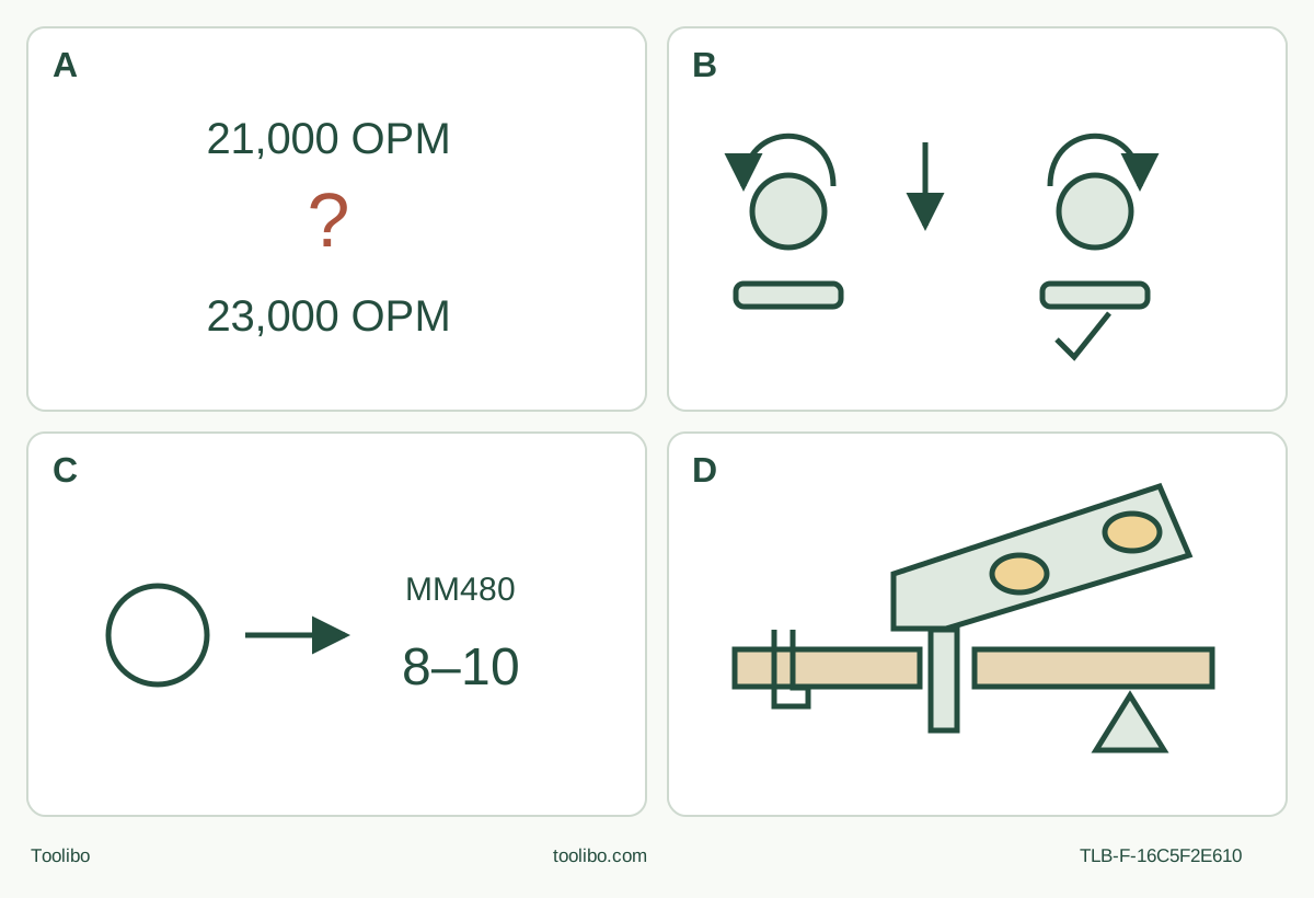
A · Resolve actual identity
Only the documented 21,000-OPM body/manual agreement is in scope. Unresolved or 23,000-OPM equipment remains held.
B · Complete the clamp
Unplug, remove the cooled old accessory and complete loosen, press, seat, release and final clockwise hand-tighten actions.
C · Separate entry from the table
Start initial plunge at medium speed for control; MM480 softwood table is 8–10, not an automatic maximum-speed entry command.
D · Plan the whole approach
Retain both insulated grips, clear vents and full blade clearance. Stop fully and unplug before acceptance or correction.
Original conceptual schematic. A does not approve either body by appearance. B is not a holder pin diagram; complete all five written actions and check isolated. C does not assign a number to medium entry. D is a grip and clearance planning cue, not a dimension, exact hand contour or proof that vents are clear on a real setup.
Stop at the speed-identity gate first
This owner project applies only to an existing US MM50 body documented for 10,000–21,000 OPM, with actual nameplate, controls and supplied instructions agreeing with 1600A014GX AC 03/2022. It is not a general setup for every current MM50 listing.
The current MM50-01 product page says a maximum of 23,000 OPM, while the complete manual linked from that very page specifies 21,000 OPM and requires Dremel accessories rated at least 21,000 OPM. That discrepancy is unresolved here. A 23,000-OPM body, unreadable or conflicting identification, or an owner unable to establish the matched system is a hold for manufacturer clarification. The manual’s 21,000-OPM accessory threshold does not automatically qualify an accessory for a 23,000-OPM machine. Do not invent a revised threshold or resolve the discrepancy by choosing whichever number is convenient.
Once that gate is satisfied, the outcome is a short, visible cut in known dry, uncoated loose softwood using an actual original MM480 HCS wood flush-cut blade. The tool’s angled housing must fit the planned approach without blocking the grips or vents. Neither the shape nor a product photograph proves clearance. The work is removed from any structure, with both faces and the exit route visible; no installed casing, hidden wiring or pipe work is included.
MM50-01 and MM50-02 are package labels, not two different owner topics. The current page identifies MM480 among its accessories, but the actual blade, rating and original identity must be checked. There is no promise that a used system or today’s box contains every required part, and no MM480U or universal-fit substitution is inferred.
Prepare the corded system and workholding
Establish OFF, wait for complete standstill and unplug before inspecting or changing anything. The matched manual specifies 120 V AC, 60 Hz; use the actual matching supply, never a DC source for the AC-rated tool or a modified plug. An unreliable switch, damaged cord, cracked housing, loose holder or suspicious condition ends preparation until qualified service has corrected it. Do not reproduce a fault with power.
Check the actual nameplate current and, if an extension is needed, its condition, rating and length. For a confirmed 5 A system, the manual’s 3–6 A row gives 18/16/16/14 AWG at 25/50/100/150 feet. Its separate metric columns give 0.75/0.75/1.5/2.5 mm² at 15/30/60/120 metres; these are separate printed selections, not direct unit conversions. Account for the actual circuit and other loads rather than treating this table as an outlet inspection. Use GFCI protection where required by the actual conditions and instructions. This project is dry; do not work in a wet or solvent-soaked area. An unexplained slow start or supply problem is not an invitation to turn the dial up repeatedly.
Choose sound stock free of nails, screws, coatings and other foreign matter. Mark the intended line and check the installed blade’s actual reach and complete oscillating envelope. Clamp the retained portion to a stable bench support. Support the waste independently so it can separate without closing the kerf. Keep clamps, support, the cord and both hands out of the complete cutting and breakthrough route. Do not hold the work by hand or use blade length as a depth rating.
Keep the area well lit, footing stable and bystanders away. Wear eye and hearing protection, protective gloves for all work and accessory changes, and suitable dust protection with ventilation and any qualified extraction equipment used under its own instructions. The manual calls for thick cushioned gloves and frequent rest breaks for vibration exposure. Keep loose clothing and hair clear. No native saw-extraction attachment is established in this selected source, and no small sample is exempt from dust controls.
Easy-Lock still needs its final hand-tightening step
Let any old accessory cool before touching it. Unplugged, turn the clamping knob counterclockwise to loosen it, press the knob and lift the old accessory bracket off the locating pins. Loosen farther only as necessary to provide room. Remove the old attachment completely before fitting the new one; do not stack blades or add a washer.
Inspect the original MM480 for cracks, breakage, bending, dullness or excessive wear. Reject suspected damage. For the matched 21,000-OPM body, establish the actual Dremel accessory rating of at least 21,000 OPM as well as its wood application. If the marking or exact information is missing, obtain clarification before proceeding.
The complete installation has five actions:
- Loosen the clamping knob counterclockwise.
- Press it so the flange extends enough to admit the accessory between flange and interface.
- Seat the blade with all locating pins engaged and its mounting area flush against the holder.
- Release pressure on the knob. The spring only holds the accessory temporarily while it is secured.
- Turn the knob clockwise and tighten it fully by hand, to the manual’s limit of no further comfortable hand turn.
There is no specified numeric torque here and no permission to use pliers or a wrench for extra force. A spring-held blade is not a completed clamp. Check the finished seating and retention while unplugged. If it remains loose or uneven, remove and refit using the same isolated procedure; unexplained wear, damaged parts or inability to secure it is a service hold, not a powered seating test.
An angled blade position is permitted only if it still engages every locating pin and lies flush before the same full tightening. The tool’s angled body does not create a new attachment angle, bendable blade rule or universal clearance allowance.
Plan the two grips and select the correct speed
With power disconnected, rehearse the approach to the visible mark. The actual front, side and lower/rear ventilation openings must remain clear. Although the comfort-grip illustration shows one hand, the operating safety text expressly requires both hands. Use the insulated gripping surfaces, keeping hands and the body away from the cutting area and never reaching beneath the stock. If the housing cannot approach while retaining both grips and clear vents, change the setup or choose another qualified method.
The slide switch runs forward to ON and backward to OFF. The separate dial retains its setting, so check it before reconnecting; do not assume the last user’s setting suits this blade and material. For the documented 21,000-OPM body, the dial has ten positions. Its printed approximate ranges at 2/4/6/8/10 are 10,000–11,000 / 11,000–13,000 / 13,000–16,000 / 16,000–19,000 / 19,000–21,000 OPM. These are ranges, not precise speeds guaranteed under load.
The MM480 table gives 8–10 for softwood. Separately, the cutting instructions say to begin an initial plunge at medium speed for control, then increase as appropriate after entry. Preserve that distinction; do not invent a numbered medium setting or treat the material table as a command to start every cut at maximum. This project does not extend the blade’s row to metal, coatings or an unidentified substitute accessory.
Make the sample without forcing the tool
After the supply, attachment, supports, dust arrangements, cord route and controls are qualified, confirm OFF and connect power. Hold both insulated grips with the blade clear of the work. Slide forward to ON and allow the selected operating speed before contacting the marked point.
Use light pressure and controlled back-and-forth passes, allowing the blade to cut a little at a time. Do not twist the tool to steer, lever it sideways in the kerf or force greater depth. Maintain the planned grip and vent clearance as the angled housing moves. Watch for stock movement and the approaching exit, keeping the waste support independent.
If the blade binds, the stock shifts, the attachment moves or an unexplained sound or vibration appears, switch OFF, wait for full stop and unplug before examining the cause. Keep hands clear of moving teeth. Correct only a clearly identified external setup issue while isolated; a damaged or unexplained system needs qualified service. Do not repeatedly restart it or borrow another model’s powered cooling routine.
Finish with an isolated acceptance decision
After complete separation, switch OFF, wait for full standstill and withdraw along the clear path before setting down. Unplug and let hot parts cool. Inspect both the cut and the attachment: the intended line and size should be achieved with full breakthrough, no uncontrolled tear-out or scorching, no shifted support and no unexplained holder movement. This is a qualitative project check, not an invented precision tolerance.
Accept a sample that meets its intended need. If it fails, correct the identified support, material, blade or technique issue before planning another sample; do not compensate with extra force. Suspected damage or unreliable controls remain a service hold.
Sanding is a separate setup. If later qualified with the actual original MM14 pad and suitable MM70W wood sheet, stop, unplug and cool before changing. Align the sheet without overhang. The manual’s brief powered flat-surface step is specifically for paper adhesion, not a blade-retention test. Work with the full pad flat and moving rather than tipping onto its point. This cut does not prove that a separate sanding or extraction system is ready, and inherited references to a control foot or scraper screw are not instructions for adding such parts to this body.
For care, unplug first, keep vents and switch areas clear without inserting pointed objects, and avoid solvents that damage plastics. The manual specifies no user-serviceable internal parts; its 50–60-hour brush-service recommendation is for a Dremel service facility, not a home opening procedure. Retain the exact nameplate, supplied document and accessory information with the tool.
Source basis: current selected US MM50-01 product/manual link; MM50 1600A014GX AC 03/2022, complete English 2–19 and actual mounting, grip, accessory, operating and extension-table figures. This is a document-based existing-owner workflow, not hands-on testing, current kit verification or resolution of the 23,000/21,000-OPM conflict.
Models referenced