
Supply, snap mount, automatic light and supported cut
A identifies GOP40-30 120 V AC 60 Hz 4 A, OSL/OSP accepted and OSM excluded, at least 21,000 OPM accessory rating and disconnected power. B presses a neutral holder onto the model-facing OSL114F accessory. C connects I/0 activation to an LED symbol and six approximate speeds. D is a plan-view paired grip cue with blade aligned through separately supported stock and 0 then unplug.
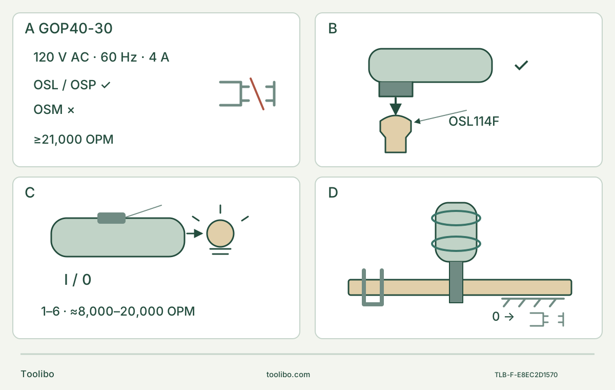
A · Match the electrical and accessory system
Use the exact healthy US body and suitable supply. OSL/OSP permission does not include OSM; accessory rating must be at least 21,000 OPM.
B · Snap in while unplugged
Face the model marking toward the holder and press until securely engaged. No bolt or washer is added; opening the lever ejects the cooled accessory.
C · Separate light from safety
Forward I runs and lights the GOP40 LED, rear 0 stops. Six settings are approximate; initial plunge uses medium speed, not an invented universal number.
D · Finish a controlled sample
Keep two-handed insulated control and a fully supported clear path, guide lightly without twisting, then stop and unplug before checking both faces.
New original schematic, not to scale. B omits detailed jaw geometry and any pin count; the arrow establishes orientation, not a powered fit test. C shows switch-linked light, not an independent illumination mode or restart protection. D is a plan view, not a blade-depth or clearance dimension: the two outlines mark two-handed grip, and actual clamps, waste support, full sweep and underside clearance must be checked. Stop, wait for standstill and unplug before acceptance.
Match the US corded body, not just the shared manual cover
This owner project uses the Bosch GOP40-30, the corded 120 V AC, 60 Hz body identified by the current US GOP40-30B product, order 0601231010 and service part 3601B31010. The product specifies 4.0 A. Confirm the actual nameplate, sound condition and applicable instructions before proceeding. The B kit label is not a second tool, and this is not a cordless GOP18V model or a regional 230 V version.
The currently linked operating manual is 2610051957, dated September 2018. Its cover also names GOP55-36, but the two columns are not interchangeable: GOP40 has a 3.0° arc, Starlock/StarlockPlus acceptance and an automatic LED; it does not gain the other body’s StarlockMax capability. The document’s age is stated rather than presenting it as a newly issued manual.
The outcome is one visible, supported separation cut on a loose piece of known uncoated solid softwood, using an actual identified Bosch OSL114F. You will qualify its fit and reach, snap it in while unplugged, make a controlled entry and complete the cut, then inspect both faces with power disconnected. No hidden-service cut, nail-cutting demonstration, scraping or sanding project is included.
Make the electrical and blade gates real
Inspect the plug, entire accessible cord, switch, housing and accessory holder while unplugged. A damaged cord, unreliable switch or insecure holder stops the project. Do not tape over a defect, modify the plug or open the tool. The source assigns power-cord service to a Bosch factory service center or authorized station.
Use a sound supply matching the actual 120 V AC, 60 Hz rating. Do not use a DC supply or infer that an adapter makes a different regional voltage suitable. Keep the work dry and route the cord away from the blade, heat, sharp edges and the eventual waste. Avoid a cord loop that can pull across the cut as you move. The manual requires GFCI protection if damp operation is unavoidable; this project instead selects a dry workspace.
If an extension is necessary, its conductors must carry the actual tool current. For the 4 A body, the manual’s 3–6 A row specifies 25/50/100/150 ft with 18/16/16/14 AWG respectively. Its separately printed metric row gives 15/30/60/120 m with 0.75/0.75/1.5/2.5 mm². Do not treat these two lists as exact length conversions or extend them by guesswork. Choose a sound suitable cord for the actual conditions; an outdoor extension must be rated for outdoor use. If supply or extension suitability is uncertain, resolve it before working.
The accessory must be a genuine identified Bosch OSL114F appropriate to the selected clean wood and rated at least 21,000 OPM. This minimum accessory rating is distinct from the tool’s 20,000 OPM maximum. Check the actual blade and its instructions for approval, condition and working reach. Reject dull, bent, cracked or otherwise suspect blades before each use.
Manual pages 7 and 10 permit OSL and OSP interfaces on GOP40 and reject OSM. An OSM blade appearing in a later generic application table is not an exception. The current product lists OSL114F, and the manual’s page 11 table describes it for wood; neither fact certifies every blade in a used kit or permits an unmarked substitute. No loose adapter, screw or washer is part of this snap-in route.
Prepare the entire cut while unplugged
Choose a manageable loose softwood sample with both faces and the underside visible. Inspect it for nails, screws, coatings and other foreign material; reject uncertainty rather than rely on the blade’s broader marketing claims. Mark a short straight separation line, identify the retained side and waste, and verify that the actual blade can complete the thickness without the holder or body striking the work.
Clamp the retained piece securely to a stable platform. Support the waste independently so separation does not drop it onto the blade or close the kerf. Keep supports and clamps outside the full oscillating envelope, not merely outside the drawn line. Check the whole approach, cut and withdrawal path, including the cord and room for two-handed insulated gripping and access to OFF. Do not hold the stock in a hand or put a hand underneath to catch the waste.
Work in a well-ventilated, orderly area with bystanders clear. Wear eye and hearing protection, suitable respiratory protection for the dust, and the protective gloves required by the manual for all work and accessory changes. Its vibration advice calls for thick cushioned gloves and frequent rest periods; gloves do not make prolonged exposure harmless. Keep clothing, hair and gloves away from moving parts. Dust collection, where provided, must be connected and used correctly; the optional OSC005 hood is sanding-only and cannot be presented as capture for this saw cut.
Snap in; use the lever only to release
Keep the plug disconnected and the switch at rearward 0. Allow an old accessory to cool. To remove it, open the release lever: the holder ejects the accessory. Provide a safe receiving surface, keep hands clear of teeth and do not catch a hot blade. Clean the holder and accessory with a clean cloth as needed.
Position the selected OSL114F so its model-number face points toward the tool’s accessory holder. Select a documented forward or left/right mounting angle that gives the checked clear path. Press the tool into the accessory until the holder’s jaws snap securely into it. The manual explicitly says opening the release lever first is not necessary for installation.
Check secure retention while unplugged. Do not add a bolt, washer or adapter, force an incomplete connection or energize the tool to see whether the blade stays on. If the correct clean accessory will not secure, stop for qualified service. An illuminated LED later will not prove that the clamp is sound.
Understand the switch, light and speed separately
The slide switch moves forward to I for ON and backward to 0 for OFF. On this GOP40 body, the LED work light turns on automatically when the switch is activated. There is no independent light-only position established here. Do not activate the tool merely to illuminate a setup with hands near the blade.
Soft start reduces starting stress, and electronic feedback helps maintain the selected speed under load. Neither establishes restart protection. Confirm 0 before connecting power and after a power interruption, then inspect safely before any deliberate restart. OFF is not a substitute for unplugging during adjustment or acceptance.
The six dial positions correspond approximately to 8,000, 10,400, 12,800, 15,200, 17,600 and 20,000 OPM. These are approximate values, not six material approvals. The manual allows speed adjustment during operation; for this sample, choose adjustments with the tool stopped and unplugged so you can recheck the setup without distraction.
For initial plunge entry, printed page 15 calls for medium speed for control, followed by an increase after the initial cut if appropriate. It does not identify a universal numbered “medium” setting. Do not replace that sequence with maximum speed simply because the blade is rated above the tool’s maximum. The manual’s low-voltage starting discussion is not permission to continue on an uncertain or faulty supply; stop abnormal behavior and resolve its cause safely.
Cut with light guidance, then accept or reject
With the blade clear of the stock, the cord routed safely, clamps secure and switch OFF, connect the qualified supply. Hold both insulated gripping surfaces firmly without blocking the vents. Keep hands away from the cutting area and underside. Start and guide the initial controlled entry along the marked line, working away from your body.
Use light pressure and a series of smooth back-and-forth passes rather than forcing the entire depth in one push. After the initial entry, increase speed only as appropriate to the blade and material. Strong vibration during the plunge indicates excessive pressure; stop and reassess the controlled setup rather than lean harder. Keep the blade aligned. Figure 6 explicitly forbids twisting, which can bind it. Do not pry or break a remaining wood bridge with the blade.
If the stock shifts, the blade binds, the cord approaches the path or abnormal heat, noise or behavior occurs, switch OFF, wait for complete stop and unplug before investigation. Do not reproduce a fault under power. Missing reach or clearance is a reason to reject this setup, not to remove a support or force the holder into the wood.
After complete separation, switch back to 0 and wait for complete standstill. Then withdraw along the checked clear path, set the tool down safely and unplug before inspecting or setting up another cut. Check both faces for the intended line and size, full breakthrough, uncontrolled tear-out, scorching and evidence of shifted support. There is no invented dimensional tolerance. Accept only the intended complete outcome; otherwise correct a documented setup issue while isolated or seek qualified service for unexplained tool behavior.
Leave the tool ready for the right next task
Unplug before cleaning. Keep vents and switch levers free of debris, without inserting pointed objects through openings. Avoid plastic-damaging solvents or disassembly. The manual’s brush examination every two to six months, special lubrication at brush changes and noisy-bearing replacement belong to qualified service, not an owner repair tutorial. Current easy-access marketing does not change that boundary, and the old warranty text is not a current warranty promise.
Sanding remains a separate qualification: the manual names pad OSL350SD while the current kit lists OSL350SPD, and this guide does not establish equivalence. OSC005 additionally needs its correct pad, hose route, material-suitable vacuum and equipment instructions; it is not for cutting, scraping or grinding. Scraping is also excluded because the shared manual contains inconsistent pressure-only and screw-head wording that must not be turned into a new operating rule for this snap mount.
Record the actual body, document revision, blade, supply/extension, supported path and isolated sample result. A successful wood cut qualifies that bounded setup, not every accessory in the combined manual or every task shown on a product page.
Models referenced