
Three gates for the corded Max wood task
Three panels show the US 120 V/60 Hz body and OSL/OSP/OSM tiers, OSM114 with the separate 21,000 OPM accessory rating and 20,000 OPM tool maximum, and clamped stock with external lighting.
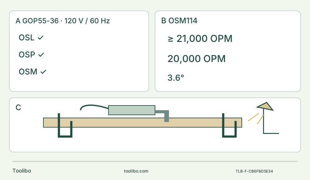
A · Match the exact 55 and supply
Confirm US nameplate and supplied manual. OSL, OSP and OSM are allowed on the 55; the shared manual’s GOP40-only LED does not transfer.
B · Identify and clamp OSM114
Use the actual Bosch HCS wood blade rated at least 21,000 OPM. Unplug, orient its model face toward the holder, snap in without opening the release lever and verify secure seating.
C · Complete a visible supported cut
Clamp and support clean softwood, keep cord and full blade envelope clear and provide external light. Use both hands, light progressive passes without twisting, then stop and unplug before acceptance.
Original schematic. B gives the accessory minimum rating and tool maximum, not the required starting speed; initial plunge uses qualitative medium speed. C shows a supported work concept with a separate bench lamp, not a built-in LED or a depth/clearance measurement. Both hands and full underside/blade clearance remain required.
Use the US 55 model, not every feature in the shared manual
This is a documented owner workflow for the US Bosch GOP55-36, using the current GOP55-36B product identity 0601231110 and the linked manual 2610051957 09/18. The document also covers GOP40-30; read the correct column. It is a currently hosted 2018 manual, not a claimed 2026 revision. Match the actual nameplate and supplied instructions. No hands-on test, current kit-content or cross-region motor claim is made.
The US 55 is a 120 V AC, 60 Hz corded tool; the product identifies 5.5 A. Use a matching, sound supply, never DC or an improvised plug conversion. This exercise assumes a suitable directly reachable outlet in a dry indoor workspace. If an extension is necessary, separately qualify it from the actual nameplate and complete manual table rather than extrapolate from a different tool. Resolve damaged wiring, an unsuitable outlet or supply uncertainty before use.
One important negative fact: the built-in LED in the shared manual is GOP40-30 only. Do not wait for a nonexistent 55 worklight or use its absence as a fault signal. Provide separate bench lighting. The 55 has a slide switch, forward I for running and rearward 0 for stopping; there is no GOP18V-34 light-only intermediate state to borrow.
Close the accessory gate before mounting
The 55 column permits Bosch OSL, OSP and OSM ranges—Starlock, StarlockPlus and StarlockMax. It still requires Bosch accessories rated at least 21,000 OPM. The tool’s maximum running frequency is 20,000 OPM; the accessory-rating requirement is a separate minimum, not a setting to dial into the tool. A matching centre alone cannot approve another brand, a worn insert or the wrong material application.
For this task, identify the actual Bosch OSM114 HCS wood plunge blade named in the matched manual’s page 11 table. Its row covers softwood, dowels, tenons and furniture components. Use a clean, untreated softwood sample, not nails or other metal. Do not substitute OSM114F merely because its name is similar: its different material row is not this project’s evidence. The accessory must be intact, sharp, suitable for the planned reach and carry the required rating. If identity or condition is uncertain, obtain manufacturer confirmation or a correctly documented replacement before proceeding.
Choose a loose sample with both faces accessible, a visible short marked cut and enough clearance for the entire blade movement. Inspect for hidden fasteners, coating and contamination; exclude installed walls, floors, pipes and unseen services. Clamp the retained stock securely to a stable bench and support the waste so it cannot fall or close the kerf. Do not reach underneath a running blade or hold the wood with one hand.
Plan the cord route behind the grip, clear of blade, clamps and waste. Wear eye and hearing protection, protective gloves as the manual requires, and respiratory protection suited to the dust. Arrange ventilation and material-appropriate dust control. Keep bystanders out and use both hands with a stable stance and clear vents. No wet sanding, solvent-soaked material or chemical-removal work belongs in this clean-wood exercise. Manual pages 3–4 and 15 supply the two-hand, support and dust boundaries.
Snap in without opening the release lever
Switch to 0 and unplug before assembly, adjustment or inspection. Let a used accessory cool and handle it carefully: opening the release lever ejects it. Keep a safe landing area and your body clear of that release path, rather than catching a falling hot blade.
Clean the holder and accessory mating surfaces with a clean cloth. With the old insert removed, orient the new insert so its model number faces the holder. Choose the working angle and press the tool into the accessory until the jaws snap into it. The release lever does not need to be opened for installation. Check secure engagement while unplugged. There is no separate screw-tightening step to borrow from a different Bosch or Milwaukee body.
A blade that rocks, fails to engage or cannot be released normally is not ready. Check correct identity and cleanliness while isolated, and obtain service for damaged components. Do not force, file or stack parts, and do not run a questionable clamp to see whether it settles. The exact installation and release procedure is on manual page 8.
Select a controlled starting speed, not the figure’s maximum
The six dial positions correspond approximately to 8,000, 10,400, 12,800, 15,200, 17,600 and 20,000 OPM. The total oscillation angle is 3.6 degrees. These describe motion, not a guaranteed cut depth, finish or safe exposure duration. Soft start and electronic feedback help maintain the selected speed but do not prevent every overload or compensate for excessive pressure.
For initial plunge entry, page 15 specifies starting at medium speed for greater control, with an increase possible after the initial cut. Do not interpret the diagram’s 20,000 OPM maximum as a command to begin at full speed or invent a universally correct numbered medium setting. Use a scrap sample and the actual blade instructions to qualify the selection. For this exercise, make setting changes with the tool OFF and clear of the work so both hands remain available during cutting.
With setup complete, check OFF, reconnect to the verified supply and hold the tool in its working position with the blade clear. Slide forward to I, allow stable running speed, then approach the marked cut under control. Use light pressure and a series of small progressive passes rather than force the full cut in one movement. Keep the blade aligned. Manual page 17 explicitly prohibits twisting while cutting because it can bind the blade; do not misread other flush-cutting wording as permission to twist or lever it.
If vibration becomes severe during entry, reduce pressure; if the stock shifts, the blade binds, the mount changes or control is lost, stop and isolate before correction. Do not deliberately stall the tool. This guide does not use the manual’s low-supply-voltage note as an electrical-fault workaround: an unverified or defective supply must be resolved, not compensated for by a higher dial position.
Complete and accept the wood sample
Finish the planned short cut while maintaining support and clear hands. Switch rearward to 0, wait for all blade motion to cease before close inspection or setting down, then unplug. Avoid contacting the hot blade or cut material. Check the completed cut in good light only after it is safe to handle.
Accept the sample when it follows the intended line and size, achieves the planned breakthrough and has no uncontrolled tear-out, scorch or evidence of shifted stock/support. Otherwise reject the result and identify whether support, blade condition, pressure or setup needs correction before another sample. No numerical tolerance or cutting-speed benchmark is invented. A longer Max-tier blade is not permission to make an unseen deep cut.
OSC004 is optional depth control, not hidden-clearance proof
If the owner actually has the matched OSC004 kit and wants a separate limited-depth practice cut, unplug first and remove the accessory. Put its bracket over the tool nose with the clamp facing rearward, close the clamp, push the correct guide into the front opening, refit the blade and set the desired depth with the red button. Page 18 distinguishes the narrow stop for straight plunge blades from the wide stop for round segment blades; do not swap those diagrams casually.
Verify that the stop is secure, the blade’s complete moving envelope remains clear and the chosen setting suits known stock thickness. A depth stop does not find pipes, prove what lies behind a board or act as an anti-kickback device. Test the setting on visible scrap and inspect the isolated result before relying on it. If the kit, guide or setting evidence is incomplete, omit this optional task rather than improvise a stop. The completed basic wood cut does not depend on owning it.
Keep OSC005 sanding and the pad-identity gap separate
OSC005 is a sanding-only dust hood. Manual page 19 excludes cutting, scraping and grinding and prohibits using the dust kit without a vacuum. It therefore cannot be fitted as this wood blade’s dust-capture solution. Use other suitable workplace dust controls for cutting rather than misrepresent the hood.
A future sanding setup requires the correct hood, independently matched backing pad and sheet, suitable hose connection and a vacuum rated for the actual material. The old manual lists OSL350SD; current accessory compatibility information uses OSL350SPD and other specific listed sanding accessories. Those identifiers are not silently interchangeable. Until the actual pad is confirmed for the body and hood, sanding remains on hold even though the saw setup is complete.
Once the exact sanding system is independently qualified, its unplugged assembly is: remove the old accessory, position the hood over the attachment area, secure its cam lever, fit the matched pad and sheet and connect the hose. The manual distinguishes VX120 for Bosch VH-series hoses, direct 22/35 mm connections such as VAC-series, and VAC024 for common 1-1/4 or 1-1/2 inch hoses. Physical hose fit does not establish dust-class suitability. Follow the complete sanding instructions, including correct-size paper, flat pad contact, light continuous movement and the specific brief sheet-adhesion step, rather than reuse a cutting-speed or metal-dust procedure.
Leave the corded system isolated and serviceable
Unplug for cleaning, accessory release and storage. Keep the holder clean and ventilation openings and switch free of debris. Do not insert pointed objects through openings or use plastic-damaging solvents such as gasoline or ammonia-containing cleaners. Do not open the tool to lubricate gears or inspect brushes: the manual’s internal maintenance belongs with Bosch factory or authorized service, as does power-cord repair.
Persistent abnormal noise, damaged mounting parts, unreliable switching or a damaged cord means stop and service, not an improvised restart routine. Store the clean disconnected body and protected, identified blade where children cannot reach them. The outcome is an accepted visible wood sample and a clearly separated status for optional depth and sanding systems—not a claim that every feature in the shared manual applies to GOP55-36.
Models referenced