
Two-stage isolation, snap-in engagement and exact controls
Three panels show complete battery removal through the secondary latch, an isolated snap-in holder over a rated OSL114 blade, and I/0 with automatic lamp and approximate eight-thousand to twenty-thousand OPM range.
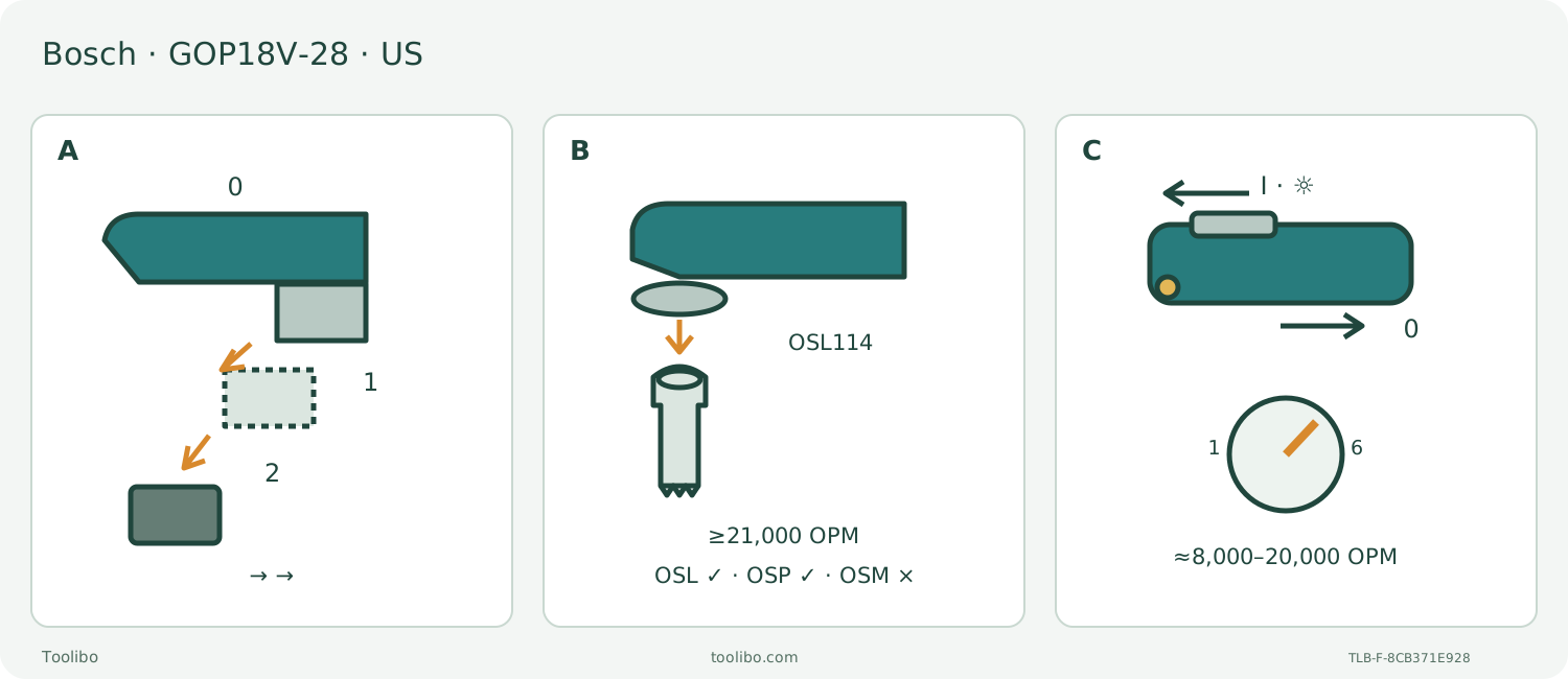
A · Complete battery removal
Select 0/OFF, wait for stop, press and slide forward, then press again and withdraw completely. Partial release at the secondary latch is not isolation.
B · Model-specific fit and snap
Use intact rated Bosch OSL/OSP accessories only, never OSM. With the battery out, model-number side faces the holder; press until jaws snap and check retention without power.
C · Simple switch, controlled trial
I starts and lights the work automatically; 0 stops. Six approximate speed settings span 8,000–20,000 OPM. Initial plunge starts at medium speed; support the sample, use two hands and isolate before acceptance.
Original schematic; engagement geometry is not a tooth count or accessory dimension. A requires two release-button presses with forward sliding to full removal, not partial release. B is snap-in without a screw or preliminary lever opening. C has no light-only stage; approximate speed limits do not prescribe the initial plunge setting.
Identify this US body before choosing an accessory
This workflow is for the US Bosch GOP18V-28, using the exact 2610051959 09/18 operating instructions currently linked by the GOP18V-28N product page. That page identifies order number 06018B601E and service part number 3601HB6011; match the actual nameplate and supplied instructions rather than assuming every similar-looking Bosch is the same body. The N bare-tool suffix does not create another mechanical model. Neither the current link nor a modern product photograph turns the manual into a new revision.
The completed project is a small, fully visible trial cut in known new, uncoated loose softwood with an actual Bosch OSL114 HCS wood plunge blade. The exact accessory table on page 12 supports wooden materials and plunge cutting in solid wood. This is not an installed-wall, nail-cutting or mystery-material project, and it does not identify the unspecified blade pictured or included with a present package.
Qualify the whole existing power system
The body is rated 18 V DC. Use an undamaged, already commissioned original Bosch system expressly covered by the matched battery/charger list, with the actual battery and charger instructions available and followed. The directly linked sheet is 2610067469, 12/2021, and explicitly includes GOP18V-28. It lists BAT620, BAT621, BAT622, GBA18V40, GBA18V63 and GBA18V80 batteries; its listed chargers are BC1836, BC1880, BC3680, BC660, GAL18V-160C, GAL18V-20, GAL18V-40, GAL18V6-80 and GAX1218V-30.
Those identities are a compatibility check, not a charging procedure. The older tool manual separately mentions BAT612 or the supplied list, whereas the linked 2021 list does not list BAT612. This project uses the explicit listed-system route; it neither declares BAT612 prohibited nor invents a charger for it. An AMPShare badge, “18 V” label or physically fitting pack does not replace this qualification. Missing component instructions, damaged packs or an uncertain combination mean pause before assembly.
The tool table’s ambient figures—0–45°C for charging and −20–50°C for operation/storage—do not override the actual component instructions or authorize new charging. Keep unused battery terminals away from conductive loose objects, never use damaged or modified packs and never open or repair one yourself.
Remove the battery completely, not just to the safety latch
Set the slide switch rearward to 0/OFF and wait for standstill. Press the battery release button and slide the pack forward. Press the button again and slide it completely out of the housing. The secondary latch is intended to prevent an accidentally loosened pack falling out; a partially released pack is not the isolation needed for setup.
Keep the battery out for mounting, adjustment, inspection and cleaning. Before later insertion, check OFF again and slide the qualified pack into the housing until it locks. Do not invent a double-click seating test or turn the motor on to check a doubtful accessory mount.
Apply the model-specific accessory limits
The compatibility tables on pages 8 and 11 admit Bosch OSL Starlock and OSP StarlockPlus, but explicitly exclude OSM StarlockMax. Some general application rows later in the manual show OSM blades; those rows do not override the exclusion for this body. Do not grind, bend or adapt an incompatible mount.
The manual also requires Bosch accessories rated at least 21,000 OPM. That accessory rating remains mandatory even though the tool’s highest no-load speed is 20,000 OPM. Inspect the actual OSL114 for identity, rating, sharpness, cracks, bending and other damage. The HCS wood row does not justify cutting hidden fasteners. If the original blade or its rating cannot be established, obtain a properly qualified accessory before continuing.
Snap in with the battery out
Wear protective gloves for all work and accessory changes; allow hot accessories to cool and keep fingers clear of sharp edges and the clamp. If another accessory is mounted, open the accessory release lever to eject it into a safe landing area. Do not catch an ejected hot blade. Clean the holder and accessory with a clean cloth when necessary.
Position the OSL114 with its model-number side facing the tool’s holder. Choose a permitted forward, left or right working orientation that keeps the whole blade path visible and preserves two-hand control. Press the holder into the accessory until the clamping jaws snap into engagement. The manual specifically says it is not necessary to open the release lever first for installation.
Check complete engagement and secure retention while isolated. This is a snap-in holder: there is no accessory screw to torque, extra washer to add or cross-system adapter recipe in this procedure. The manual’s separate sanding-sheet adhesion step is not permission to power-test blade seating. If the holder cannot retain the correct undamaged accessory, stop for authorized service.
Support a sample that lets you see the whole cut
Choose stock whose intended cut area, both faces and underside are known and accessible. Check for foreign material. Mark a short cut only after confirming the actual blade’s usable reach and the complete moving envelope; no arbitrary sample thickness is a manufacturer capacity here.
Clamp the retained work to a stable platform and support the waste independently so it cannot drop, trap the blade or need a hand near the cut. Keep the bench, clamps and both hands clear of the teeth and underside. Arrange the task so both hands hold the tool throughout cutting, with balanced footing and unobstructed ventilation openings. A supported loose sample is the complete project; no hidden service location is inferred from it.
Use eye and hearing protection, the appropriate dust/respiratory protection and effective material-specific dust controls and ventilation. Wear the required protective gloves, including the manual’s cushioned-glove and rest-break precautions for vibration; keep gloves, clothing and hair away from moving parts. Do not work in wet or solvent-soaked material. OSC005 is a sanding hood, not a dust-capture solution for this saw cut.
Start at a controlled speed, not a borrowed dial number
The six dial settings correspond approximately to 8,000, 10,400, 12,800, 15,200, 17,600 and 20,000 OPM. Those are approximate no-load references, not loaded performance measurements or an equivalence to another Bosch’s settings. Select a speed appropriate to the blade and material and practice on the prepared scrap first.
For the initial plunge, page 16 specifically says to begin at medium speed for control; speed may be increased after the initial cut. It does not prescribe one exact numbered initial setting. Set up with the battery out, check the switch is OFF and then insert the qualified pack securely.
Slide the switch forward to I to start with the blade clear of the work. The worklight turns on automatically with the switch; there is no separate light-only stage like the GOP18V-34. Soft start and electronic feedback do not make an unsecured blade or overloaded cut safe.
Make the cut, then decide whether the sample passes
Guide the blade into the marked area with light pressure. Allow the accessory to cut rather than forcing it. Use controlled passes and keep the tool aligned; do not twist it in the cut, bend the blade, pry the last fibers or cover the vents. Increasing pressure to overcome poor progress is not a substitute for checking the blade, stock and support.
Stop if the stock shifts, the blade binds, the attachment becomes uncertain or behavior is abnormal. Select 0/OFF, wait for complete stop and remove the battery before any physical correction. Do not reproduce an abnormal event under power or import another model’s thermal-reset routine. Persistent or unexplained faults require qualified service.
At completion, select OFF, let the accessory stop and isolate the tool before handling the sample or blade. Inspect against the intended line and size: the cut must be fully through as planned, with no uncontrolled tear-out, scorching or evidence that the support moved. A failed sample calls for a documented setup correction or qualified help before another attempt; this guide supplies no structural tolerance or hands-on performance claim.
Keep optional systems separate from a ready cutting setup
OSC004 is the documented optional depth-stop kit. Its isolated installation removes the accessory, places the bracket on the nose with the clamp facing rearward, closes the clamp, inserts the appropriate guide, reinstalls the accessory and sets depth with the red button. The narrow stop is for straight plunge blades; the wide stop serves round segment blades and other illustrated guided cuts. It is not a hidden-service detector or a guarantee against overcutting. This first sample does not require it.
A sanding project needs a separately qualified backing pad, sheet and material-suitable extraction system. The old manual names OSL350SD while the current product names OSL350SPD and other pad variants; do not silently treat those IDs as interchangeable. OSC005 is only for sanding, never cutting, scraping or grinding, and never without a suitable vacuum. Its full mounting/hose and actual extractor instructions must be satisfied before sanding; this wood cut does not close that separate setup.
Isolate, care and record a service hold when needed
After use, keep OFF selected and remove the battery. Clean the holder as documented and keep vents and switch areas free of foreign matter without poking pointed objects into openings. Avoid plastic-damaging solvents such as gasoline or ammonia-containing cleaners. The tool is lubricated ready for use; no improvised lubricant or internal adjustment is required.
There are no user-serviceable internal parts. The manual recommends authorized Bosch service and periodic motor examination; it does not authorize opening the body at home. Keep the exact body, manual revision, blade identity and power-system instructions together. The outcome is either an accepted loose-wood trial with the tool left isolated, or a clear accessory, power or service hold—not an invitation to force an uncertain system into use.
Models referenced