
Bolt, speed and extraction are separate gates
Three panels show Starlock only with a schematic 30° bolt stack, sanding and RIFF maximum 4 versus wood maximum 6, and extraction requirements at the tool connection.
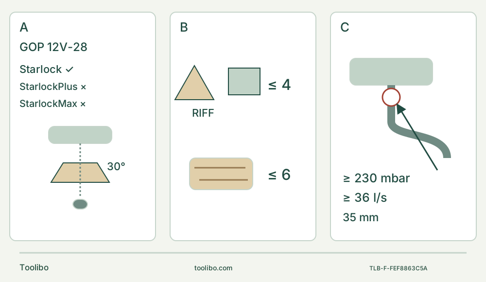
A · Seat and bolt the Starlock accessory
Remove the battery, orient the depressed centre downward with text readable above, engage a 30° position and tighten the original bolt head flat using the hex key. Remove the key.
B · Respect different speed limits
Wood sawing has a recommended maximum 6; sanding, RIFF, plastic and metal are limited to 4 or any lower accessory limit. Select the actual trial setting deliberately.
C · Qualify installed sanding extraction
Always extract during sanding. Require at least 230 mbar and 36 l/s at the tool connection; 35 mm hose is recommended. The attachment is not a saw-blade hood.
Original schematic. A does not depict an exact cam count or substitute for the depressed-centre orientation. B shows upper limits, not starting settings. C applies to the sanding-plate-only extraction system: both performance values are required, while 35 mm hose size is recommended.
Identify the UK bolt-mounted body
This is a complete first cutting setup for an existing UK Bosch GOP 12V-28, product 06018B5002, with the actual body and supplied instructions matched to the current linked E66 manual dated 10 June 2026. The UK declaration identifies type 3 601 HB5 001. It is not the GOP18V-34 snap-in body: this smaller machine requires its clamping bolt and hex key. No current kit contents or hands-on performance claim is made.
The finished task is one short edge-start cut through known, loose, untreated softwood, followed by an isolated acceptance decision. The manual lists the Bosch AIZ 32 EPC Starlock HCS blade for softwood; use an intact, correctly identified example with its own instructions. Do not replace it with a blade selected solely because its colour or centre opening looks similar. Unknown coatings, embedded metal and installed walls are outside this project.
Qualify the already commissioned power system
The tool is rated 12 V. E66 lists GBA 12V battery and GAL 12 / GAX 18 charger families, but a family name does not replace the exact owner-approved pack/charger pairing. Continue only with an intact genuine compatible pack, its approved charger and their actual instructions already independently confirmed. This article does not supply charging diagnostics or select a new charger from its connector shape.
The tool document recommends 0–35°C for charging and allows −20–50°C for operation/storage, with reduced performance below 0°C. Apply any narrower actual pack or charger requirements. Keep batteries away from heat, moisture and loose metal; do not use damaged or modified packs, open them or bypass their protection.
Set the slide switch rearward to 0 before inserting the charged pack until it clicks into place. For every assembly, adjustment, cleaning or storage operation, remove the pack: press the release buttons and pull it out without force. A switch setting or a depleted battery is not a substitute for removal. Complete the following setup with the battery separate from the tool.
Build a stable, visible work area
Check both faces and the full cutting path for foreign objects. Clamp the retained stock to a stable platform. Keep the blade’s complete approach and below-work travel clear of the bench, clamps, hands and cables; support the waste so it does not pinch the blade or drop dangerously. Do not hold stock against your body. Mark a short line accessible from the edge rather than beginning with a blind plunge.
Wear suitable eye, hearing and breathing protection. Ventilate and take dust-reducing measures for the material; E66 does not exempt cutting from dust control. Keep bystanders clear and avoid dust accumulation. Hold the insulated grip with both hands, keep vents unobstructed and arrange your grip so you can operate the switch without releasing the handle. A confined position that prevents these conditions is not a suitable first setup.
Seat the cams and tighten the bolt
Only Starlock is approved for this body; StarlockPlus and StarlockMax are excluded. With the battery removed and the blade cool enough to handle, wear protective gloves against sharp edges. Use the hex key to loosen the clamping bolt and remove an existing accessory if necessary. Keep the specified bolt and key available; no tool-free lever procedure applies here.
Place the selected accessory on the holder with its depressed centre facing downward and its printed text readable from above, as in the actual assembly figure. Engage it with the holder cams at a suitable position. There are twelve positions separated by 30°; choose a direction that permits safe control and clearance rather than forcing an intermediate angle.
Secure the accessory with the clamping bolt. Tighten using the hex key until the rounded bolt head lies flat against the accessory, then verify that the accessory is seated securely. The manual gives no numerical tightening torque. Do not invent one, substitute a random screw or use impact tightening. Remove the hex key before power is available. If the accessory will not seat, the bolt will not finish correctly or the holder is damaged, stop and obtain the correct part or qualified service rather than attempting a powered fit test.
Select speed for the material, not for the tool’s maximum
The 12 V drive covers 5,000–20,000 oscillations per minute with 1.4° movement to each side, 2.8° overall. These specifications do not mean every accessory should run at maximum speed. E66 recommends a maximum setting of 6 for sawing wood; plastic and metal sawing must not exceed 4. Sanding and RIFF accessories also have a maximum of 4, subject to any lower accessory limit.
For this softwood sample, select a controlled trial setting within the blade’s instructions and the wood limit. The manual says practical tests determine the required setting; it does not prescribe one universal starting number. Do not import the US GOP18V-34 frequency chart or its accessory classes into this UK body.
Complete and inspect the cut
Recheck mounting, supports, dust controls and clearance. Insert the approved pack with the switch at 0. Hold the tool securely and start clear of the wood by sliding forward until I is visible. Bring the blade to the marked edge with consistent low contact pressure. Move the tool appropriately along the cut rather than holding it in one spot until the accessory overheats or jams. More force can reduce performance and cause binding.
Keep hands away from the cut and never reach below the stock. Support must remain effective through breakthrough. If the work shifts, the blade binds, abnormal vibration appears or the accessory overheats, switch OFF and wait for a full stop; remove the pack before correcting the cause. Do not try to recover control by leaning harder on the machine.
After the intended separation, switch rearward to 0 and wait until the accessory stops before setting the tool down. Remove the battery before clearing waste, touching the blade or examining the cut, and allow hot parts to cool. Accept the sample only when the intended line and size are achieved, the required separation is complete, and there is no uncontrolled tear-out, scorching or evidence of support movement. No numerical accuracy claim is implied. A failed sample calls for correction and another controlled trial before valuable work.
Distinguish indication from automatic shutdown
The tool’s three green charge-indicator LEDs illuminate for five seconds after startup. E66 assigns three steady lights to 67–100%, two to 34–66%, one to 11–33%, one flashing to 1–10%, and three flashing to 0%. These are the matched tool’s displayed charge ranges, not a battery health or remaining-runtime measurement.
Overload or battery temperature outside the permitted range can reduce speed or stop the tool. If it shuts down automatically because the battery is flat or overheated, deliberately switch OFF. Charge under the actual approved charging instructions or allow the battery to cool as appropriate before a deliberate restart. Do not leave the switch at I while exchanging a pack, repeatedly press for more operation after a cutoff or borrow another model’s no-load cooling routine. Persistent faults require service.
Treat sanding as a separately completed extraction system
The cutting sample does not make the tool ready for sanding. For that later task E66 requires extraction every time, with the accessory and depth stop removed while fitting the extraction assembly. Slide the correct extraction unit fully over the holder onto the tool collar and close its clamping lever. It is designed only for the sanding plate, not as a saw-blade capture hood.
For the version without Click & Clean, engage the extractor hose in the adapter and fit the adapter to the extraction outlet. For the Click & Clean version, the hose can engage directly in the outlet, or the specified adapter can be used as illustrated. Select the route that matches the actual assembly rather than forcing a connection.
The required installed performance is at least 230 mbar vacuum and 36 l/s flow at the tool’s extraction connection. A 35 mm hose and class M filtration are recommended; the extractor must suit the actual dust. A vacuum’s advertised motor rating or free-air value alone does not establish those installed requirements. Stop if suction falls and resolve the cause. Fit the approved sanding plate and clean abrasive, align extraction holes, keep sanding at or below 4 and obey lower accessory limits. Do not reuse metal-used abrasive on other materials. Empty the dust container before breaks in accordance with the extraction instructions because hot or contaminated sanding dust can ignite.
Finally, with the pack removed, keep tool and vents clean and retain the correct bolt, key and documentation together. Do not open the tool or battery as a routine maintenance step. A missing safety-critical part or unresolved fault is a service boundary, not a reason to improvise the next project.
Models referenced