
Engagement, installed extraction and complete face control
A separates an isolated release/ejection cue from a downward press-engagement cue over a neutral triangular plate. B shows at least 220 mbar and at least 34 l/s together at a connection cue. C shows maximum level 4 and an eye/light warning. D shows a clamped broad face, plate and two grip-planning highlights.
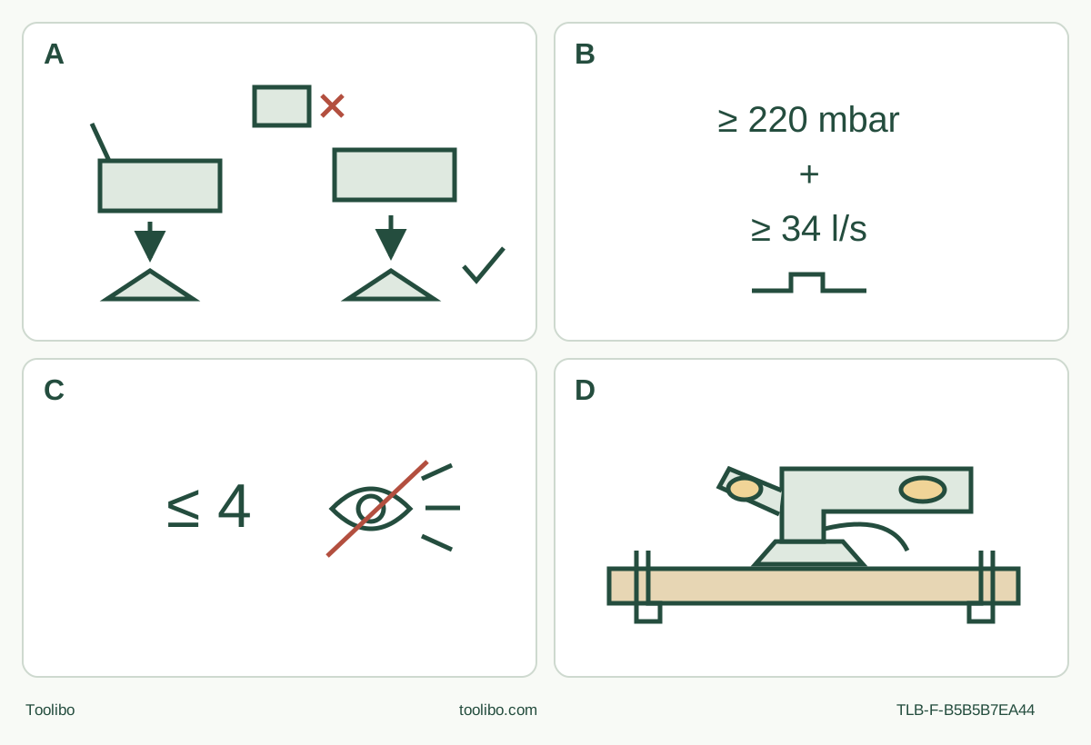
A · Release and press-engage
Battery out, fully open AutoClic to eject old attachment; press the tool onto the correctly oriented plate until audible engagement and check isolated.
B · Qualify both installed values
Matching native extraction must establish at least 220 mbar and 34 l/s at the tool, under actual extractor instructions.
C · Keep the ceiling and light warning
Sand no higher than level 4 and respect lower accessory limits. Do not look directly into the automatic light band.
D · Complete and judge the face
Use two hands and light consistent pressure. Switch 0, wait full stop and remove the battery before accepting or correcting the surface.
Original conceptual schematic. A is not a counted holder or added lever-closing instruction; follow the exact AutoClic sequence. B requires both quantities at the tool connection, not a free-air specification or improvised measurement. C is a ceiling and no-direct-look warning, not an optimum speed or lamp fault code. D is a clearance/grip cue, not exact hand anatomy or a finish guarantee.
Establish the exact cordless AutoClic system
This project uses an existing UK AdvancedMulti 18, order 0603104000, whose actual nameplate, controls and supplied instructions agree with operating manual 1 609 92A E60, July 2026. The separately linked F1H UK declaration identifies 3 603 A04 000; it establishes identity, not mounting instructions. Older B1B instructions and other-language downloads are not pooled into this procedure. A battery-kit listing is not another tool model or a promise about equipment already in your possession.
The task is to level and finish the accessible face of a securely supported, dry, clean, uncoated wood sample using the actual original AVZ 93 G plate and a suitable original Bosch Delta 93 mm wood sheet. Completion means inspecting the isolated sample and deciding whether its intended surface is acceptable. There is no installed-work, paint-removal or cutting claim here.
Although this body has AutoClic, its E60 compatibility diagram approves Starlock only and crosses out StarlockPlus and StarlockMax. The mechanism ejects and press-engages the accessory; do not add a magnetic positioning step, clamp bolt, hex key or another model’s lever-closing ritual. The correct parts and the actual audible engagement matter more than the system name.
Three prerequisites that cannot be solved by a trial run
First, the power system must already be commissioned under the actual battery and charger instructions. The manual specifies PBA 18V…W-. batteries and AL 18… chargers, excluding AL 1814 CV, AL 1820 CV and AL 1860 CV with these batteries. Do not infer a new named charging pair or compatibility with another Bosch battery family. Damaged, modified or suspect packs and tools are not candidates for a test run.
Second, identify the original AVZ 93 G plate, a sound original auxiliary handle, and an appropriate intact original wood sheet. The current exact product names the 93 mm plate as 2 609 256 956, but the actual accessory still needs checking. E60’s sheet table gives 80/100/120 for levelling slight irregularities and 180/240/320/400 for fine finishing, all within levels 1–4. Select for the actual surface; this is not a guarantee that a particular grit is supplied or that a fixed sequence fits every wood. Do not use a sheet previously used on metal.
Third, sanding requires the complete matching Figure C extraction arrangement. With the installed system connected at the tool, E60 requires at least 220 mbar vacuum pressure and at least 34 l/s flow, not one or the other and not merely an extractor’s disconnected maximum specification. The manual recommends a 35 mm hose and HEPA or dust class M filtration. For dry dust that is especially harmful to health or carcinogenic, it requires a special dust extractor. Establish the actual extractor’s material suitability, safe use and installed requirements through its instructions and qualified equipment evidence. A snug hose, audible suction or a small sample does not establish compliance. If the native hood, adapter, hose or installed performance cannot be established, hold the sanding project for the missing equipment or qualified clarification.
Isolate, inspect and arrange the face
Move the switch rearward to 0 and wait until the tool is completely still. Press the battery release button and pull the pack fully out without force. Also isolate the extractor under its own instructions. Wear protective gloves for accessory changes and allow a hot old attachment to cool. Inspect the holder, AutoClic lever, housing, switch, handle, pad, sheet and accessible original connections. Any cracking, looseness, unreliable control or unexplained damage requires qualified correction rather than powered testing.
Clamp known sound wood on a stable platform, with the whole target face reachable and the clamp heads outside the pad, housing and hose sweep. Inspect for foreign matter, metal and unknown contamination. Keep the workpiece and area dry; no liquids or solvent treatment. Good light, ventilation, stable footing and a clear bystander zone are prerequisites. Wear eye and hearing protection and suitable respiratory protection. E60 requires dust-reducing measures and suitable breathing protection; extraction is not an alternative to the other necessary PPE.
Plan the actual working stance before inserting a battery. Screw the original sound auxiliary handle into the left or right thread according to the approach. Do not alter a handle or continue with one that is damaged. Hold this tool firmly with both hands, keep ventilation slots open and ensure the switch can be operated without releasing the handle. Arrange the hose so it cannot drag the tool or trip the operator.
Eject the old accessory, build extraction, then engage the plate
With the battery still removed, open the AutoClic lever all the way to eject a fitted old accessory. Keep hands out of the release path and handle the cooled attachment with gloves. Remove any fitted segment-blade depth stop. Neither an old accessory nor that stop belongs beneath the sanding assembly.
Slide the actual matching extraction hood fully over the holder and onto the collar. Turn it to a useful direction, not directly underneath the tool, and close the hood’s own clamping lever. That hood lever is distinct from the AutoClic release lever. Figure C’s extraction assembly is sanding-plate-only: it is not blade dust capture, even though the body can perform other operations.
Place the original plate on a level surface with its depressed centre down and upper text readable. Turn it to the required working orientation, then press the tool onto it until it audibly engages. Check that it is securely seated while the power remains isolated. Do not substitute the sound of the extractor for the engagement click, add loose hardware or run the tool to test an uncertain attachment. Failure to engage securely is a hold for correct identification or service.
Tap debris from the plate’s hook-and-loop surface. Align one edge of the selected original sheet with the plate, place it down and press it firmly on, matching its punched holes to the plate holes. Remove a sheet by lifting a corner and peeling it away. No powered adhesion routine is specified.
Insert the matching dust adapter into the hose until it clicks, attach the adapter to the hood outlet and connect the hose to the actual qualified extractor. Complete the extractor’s own collection-system preparation and checks. Do not assume that a hood from a similar Bosch model, or a generic hose adapter, reproduces Figure C or preserves the required installed performance.
Work a complete surface without forcing the tool
Confirm the switch remains at 0 and the setup is complete. Insert the already qualified charged battery until it clicks into its holder. Start and verify the extractor under its instructions before making dust. Set an appropriate sanding level no higher than 4, respecting any lower limit on the actual accessory or packaging. The wood-sawing maximum of 6 is irrelevant to this sanding setup.
With both hands controlling the tool and the plate clear, slide the switch forward to I. The 180° light band switches on with the tool; do not look directly into it. Bring the plate onto the accessible wood face under control. Move across the intended area with consistent low pressure. Excess pressure increases wear and can prematurely damage the plate; it is not a substitute for a suitable sheet or careful coverage.
Keep the plate from tipping into a clamp or over an unintended edge. This task covers a broad face, rather than concentrating all force on a point. If local heating develops, reduce oscillation speed and pressure and allow the sheet to cool at intervals. Stop for lost extraction, moving stock or sheet, scorching, unusual vibration or any other abnormal condition. Switch off, wait for standstill and isolate both systems before examining the cause. Do not continue sanding while trying to diagnose suction by sound or feel.
Before a break, empty the dust collection under the actual extractor’s instructions. Avoid overheating and accumulation of dust, especially mixed residues that may ignite. Unknown coatings and solvent-contaminated wood remain outside this project; a dust system cannot make unidentified material safe.
Acceptance, signals and storage
At the end of a pass, move the switch back to 0, wait for complete standstill before setting the tool down, and remove the battery before touching the sheet or checking the wood. Isolate the extractor before its cleaning or checks. Accept the surface only if the intended face is uniformly satisfactory for the planned next step, without unwanted gouges, rounded edges, heat marks or evidence that the work moved. Otherwise record the remaining defect and correct the isolated setup or sheet choice before another qualified pass. No numerical finish tolerance or automatic readiness for coating is claimed.
Do not confuse the displays. The running tool’s three, two and one steady green lights indicate approximately 75–100%, 40–75% and 15–40%; one slow green flash indicates approximately 0–15%. Flashing red means tool overload. An optional battery indicator has four green lights and different bands, and should be checked only at standstill under the actual pack instructions. Neither display establishes battery health or guarantees remaining runtime.
After an automatic stop caused by an empty or overheated battery, explicitly switch OFF. E60 permits appropriate charging or cooling before restarting; that does not authorise a charging experiment, an immediate powered fault test or bypassing repeated unexplained stops. Unresolved faults require qualified service, without opening the tool or pack.
Keep temperature contexts intact: the tool table recommends 0–35°C for charging and permits −15–50°C for tool operation/storage, with limited performance below 0°C. The battery-handling paragraph separately allows −20–50°C storage for the battery; it is not a wider tool operating range. Actual battery/charger instructions remain mandatory. Store the isolated, cooled system clean and dry, keep vents unobstructed, and preserve the ten-digit nameplate identity and exact instructions for service.
Evidence: AdvancedMulti 18 E60 original instructions, English 16–24 and Figures A–C; current exact UK product listing for original plate identity; F1H UK declaration for type identity only. This is an instruction-based project, not a hands-on performance report.
Models referenced